A terminal fitting and a crimping method

A terminal joint and terminal connection technology, which is applied in the field of terminal joints and its connection, can solve problems such as hindering the insertion of retainers, and achieve the effect of preventing widening

Inactive Publication Date: 2010-02-10
SUMITOMO WIRING SYST LTD
View PDF2 Cites 11 Cited by
  • Summary
  • Abstract
  • Description
  • Claims
  • Application Information

AI Technical Summary

Problems solved by technology

In the case where the holder for holding the terminal fitting is installed behind the connection part of the terminal fitting, if the core wire is bent upward behind the

Method used


Image

  • A terminal fitting and a crimping method
  • A terminal fitting and a crimping method
  • A terminal fitting and a crimping method

Examples


no. 1 example

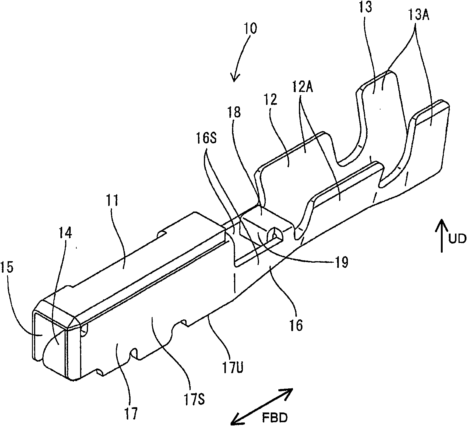
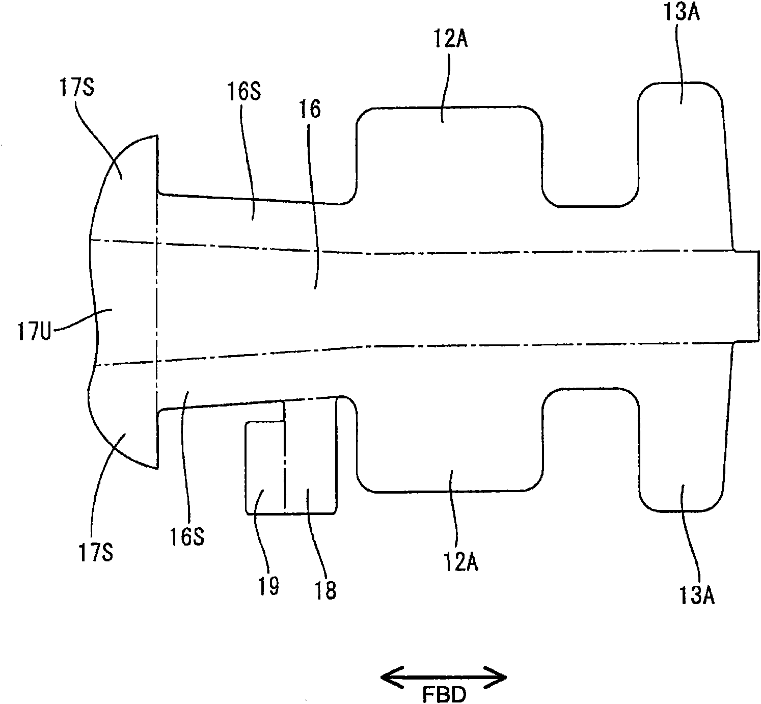
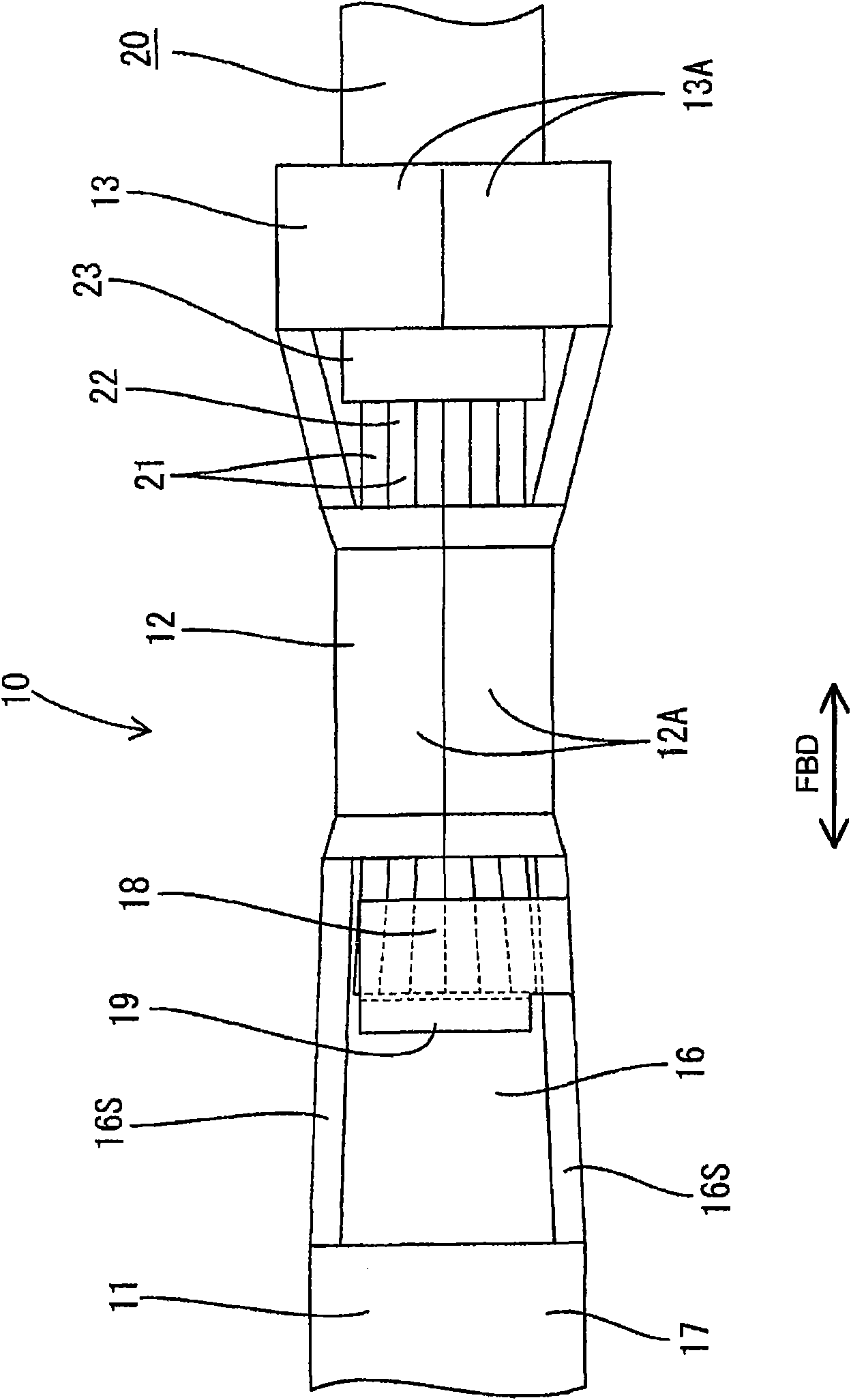
[0055] Refer below Figures 1 to 5A first preferred embodiment of the present invention is described. In the first embodiment, the present invention is applied to the female terminal fitting 10 . By stamping or stamping or cutting a substantially flat conductive (preferably metallic) sheet into a specific (predetermined or predeterminable) shape (in particular using a press-forming machine) and bending the cut or punched conductive (metallic) sheet , folding and / or embossing to form the terminal fitting 10 of the first embodiment. The terminal fitting 10 includes a connecting portion 11 connected to a mating male terminal fitting (not shown), and preferably at least one wire barrel 12 and / or at least one insulating tube 13 sequentially formed behind the connecting portion 11 . In the description below, figure 1 The upper, lower, lower left (towards the side of the connecting portion 11) and upper right sides are called upper, lower, front and rear sides.

[0056] The conne...

no. 2 example

[0080] Refer below Figures 6 to 8 A second preferred embodiment is described. The wire harness of the second embodiment is such that the terminal fitting 120 is connected to the front end portion of the electric wire 110 ( Figure 6 The left end in ) is electrically connected. The electric wire 110 is composed of a conductor 111 (preferably formed by twisting a plurality of thin metal wires) as a core wire and an insulating coating 112 at least partially surrounding the conductor 111 . At the front end portion of the electric wire 110 , as a preparation for connection with the terminal fitting 120 , the insulating coating 112 is removed in advance, thereby exposing the front end portion of the conductor 111 . Copper, a material having a higher rigidity than copper such as aluminum, or a material having a lower electrical conductivity than copper such as aluminum is preferably used as the material of the conductor 111 .

[0081] The terminal fitting 120 is specifically a fe...

no. 3 example

[0091] Refer below Figures 9 to 11 A third preferred embodiment of the present invention is described. The wire harness of the third embodiment differs from the second embodiment in the configuration of the terminal fitting 140 . Since other configurations are similar or identical to those in the second embodiment, similar or identical configurations are denoted by the same reference numerals, and their structures, functions, and effects will not be described again.

[0092] Similar to the second embodiment, the terminal fitting 140 of the third embodiment has a coupling portion 142 formed between the connecting portion 141 and the wire crimping portion 145 and is formed with one or more, preferably a pair of laterally symmetrical restricting portions 152 and a pair of (preferably also substantially laterally symmetrical) reinforcements 151 . One or more, preferably a pair of horizontal extensions 146 extending inwardly substantially parallel to the bottom plate 143 are for...


PUM


Abstract

An object of the present invention is to provide a terminal fitting capable of preventing an end portion of a wire from becoming wider. A terminal fitting 10, 120, 210, 230 is provided with a connecting portion 11, 121, 211 to be connected with a mating terminal, a wire barrel 12, 126, 212 to be crimped into connection with an end portion of a wire 20, 110, 220, and a restricting portion 18, 152,218A, 231 arranged at a side closer to the connecting portion 11, 121, 211 than the wire barrel 12, 126, 212 and facing a placing surface of a bottom plate 16, 123, 216 where the end portion of the wire 20, 110, 220 is to be placed and capable of restricting an upward movement of the end portion of the wire 20, 110, 220. The restricting portion 18, 152, 218A, 231 is arranged between the wire barrel 12, 126, 212 and the connecting portion 11, 121, 211. Thus, an upward movement of the end portion of the wire 20, 110, 220 can be prevented.

Description

technical field [0001] The present invention relates to a terminal fitting including a wire barrel crimped to be connected to an end of an electric wire and a connection method thereof. Background technique [0002] For example, a terminal fitting disclosed in Japanese Unexamined Patent Publication No. 2004-303526 is conventionally known as this type of terminal fitting. The terminal fitting is formed with a wire barrel behind a connecting portion connected to a mating terminal. Reference is also made to Japanese Unexamined Patent Publication No. 2005-222815. [0003] The lugs are crimped to connect to the exposed core wires at the ends of the wires. The wire barrel is crimped at a position where the front end of the core wire protrudes forward, thereby crimping the entire wire barrel to be connected to the core wire. [0004] When the wire barrel is crimped to be connected to the end of the electric wire, the front end (portion protruding forward from the wire barrel) of...

Claims


Application Information

Patent Timeline
IPC IPC(8): H01R4/18H01R4/58H01R13/02H01R43/04
Inventor 田端正明武田和亚希安达秀绪
Owner SUMITOMO WIRING SYST LTD
Why Eureka
Try Eureka