
Chip-type contact of electric connector for terminating cable

A technology for electrical connectors and contacts, applied in the direction of contact components, connections where permanent deformation works, etc., can solve the problems of deformation and damage of side walls, lack of support and protection, etc., and achieve the effect of reliable structure

Inactive Publication Date: 2013-01-30
CHINA AVIATION OPTICAL-ELECTRICAL TECH CO LTD
View PDF0 Cites 0 Cited by
  • Summary
  • Abstract
  • Description
  • Claims
  • Application Information

AI Technical Summary

Problems solved by technology

In addition, sheet contacts formed by bending and stamping technology have been widely used in electrical connectors. This type of sheet contact is generally composed of two side walls connected by bridge parts, and a receiving space and heat dissipation can be formed between the side walls. channel, but the bridging part of this type of sheet contact can only provide overstress protection from the edge to the two side walls, and the middle part of the two side walls lacks reliable support protection, and some contact tails also extend integrally for terminating cables. Crimp structure, the side wall of the contact is easily deformed and damaged when crimping

Method used


Image

  • Chip-type contact of electric connector for terminating cable
  • Chip-type contact of electric connector for terminating cable
  • Chip-type contact of electric connector for terminating cable

Examples


Embodiment Construction

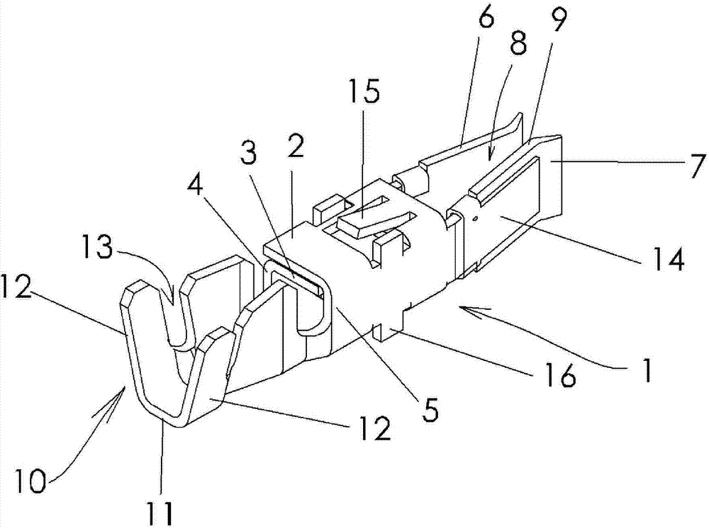
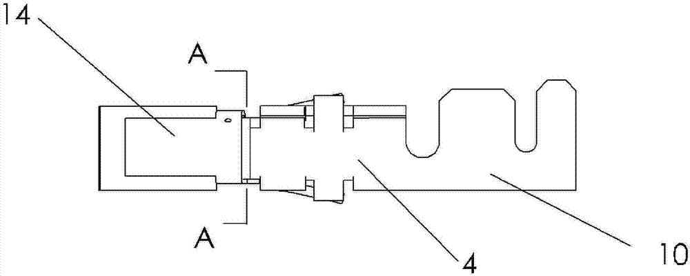
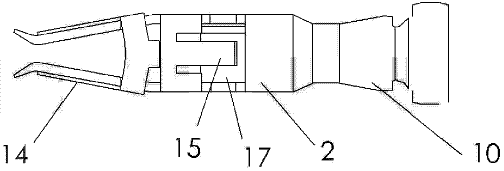
[0019] Such as Figure 1 to Figure 5 As shown, an embodiment of the sheet contact of the present invention, the main body of the contact is a receptacle contact formed by punching and bending a metal sheet, with a front plug-in terminal and a rear clamp structure 10 , and a sheath 14 is set on the plug-in end. The middle part of the contact piece is a rectangular hollow frame body 1 with a cross-section surrounded by surrounding wall panels. The top surface of the frame body 1 is formed by overlapping two layers of top wall panels 2 and 3. The side wall panels 4 and 5 respectively extend from the panels 2 and 3, and the bottom surface of the frame body 1 is a bottom wall panel 6 bridged between the two side wall panels, and the two layers of top wall panels 2 and 3 are close to the inside The edge of the top wall plate 3 leans against the opposite side wall plate 5, forming a reliable support protection between the opposite side wall plates, preventing the wire clip structure...


PUM


Abstract

The invention discloses a chip-type contact of an electric connector for terminating a cable. A hollow frame body with a rectangular cross section, surrounded by peripheral wall plates, is arranged inthe middle of the contact, wherein the top face of the frame body is formed by overlapping two layers of top wall plates, the side faces of the frame body are formed by side wall plates respectivelyextending from the two layers of top wall plates, the bottom face of the frame body is a bottom wall plate bridged between the two side wall plates, and the edge of one top side plate which is nearlyinside is butted on the opposite side wall plate. Two cantilever girders arranged oppositely at intervals are arranged at the front part of the contact, the two cantilever girders integrally extend forwards from the two side wall plates of the frame body, and a receiving space for receiving a male contact is limited between the two cantilever girders; a wire clamp structure which integrally extends backwards from the frame body is arranged at the back of the contact. The top wall plates of the hollow frame body can be butted on the corresponding side wall plates to form support protection, thereby ensuring that the wire clamp structure of the contact does not influence the frame body at the front and middle part in wire pressing so as to avoid contact distortion.

Description

technical field [0001] The present invention relates to contacts for electrical connectors. Background technique [0002] The contacts used in the existing electrical connectors, especially in the power circuit, in order to reduce the influence of the temperature rise of the contacts on the circuit where the electrical connector is located, the electrical connector is required to have a good heat dissipation structure, and the male contact and The electrical contact of the receptacle contact is reliable after mating, and the contact resistance is as small as possible to meet the requirements of less heat generation and good heat dissipation effect in the process of large current transmission. In addition, sheet contacts formed by bending and stamping technology have been widely used in electrical connectors. This type of sheet contact is generally composed of two side walls connected by bridge parts, and a receiving space and heat dissipation can be formed between the side w...

Claims


Application Information

Patent Timeline
Patent Type & Authority Patents(China)
IPC IPC(8): H01R13/11H01R4/18H01R13/20
Inventor 韩兆春
Owner CHINA AVIATION OPTICAL-ELECTRICAL TECH CO LTD
Learn More