
Airfoils with automatic pitch control

A technology of wings, moving parts, applied in the field of wings, to achieve the effect of a compact automatic pitch control solution

Inactive Publication Date: 2012-10-10
大卫・劳森
View PDF8 Cites 0 Cited by
  • Summary
  • Abstract
  • Description
  • Claims
  • Application Information

AI Technical Summary

Problems solved by technology

This approach is problematic because the magnitude of the moment is affected not only by the apparent flow direction, but also by the apparent flow velocity, which varies widely during rotation

Method used


Image

  • Airfoils with automatic pitch control
  • Airfoils with automatic pitch control
  • Airfoils with automatic pitch control

Examples


Embodiment Construction

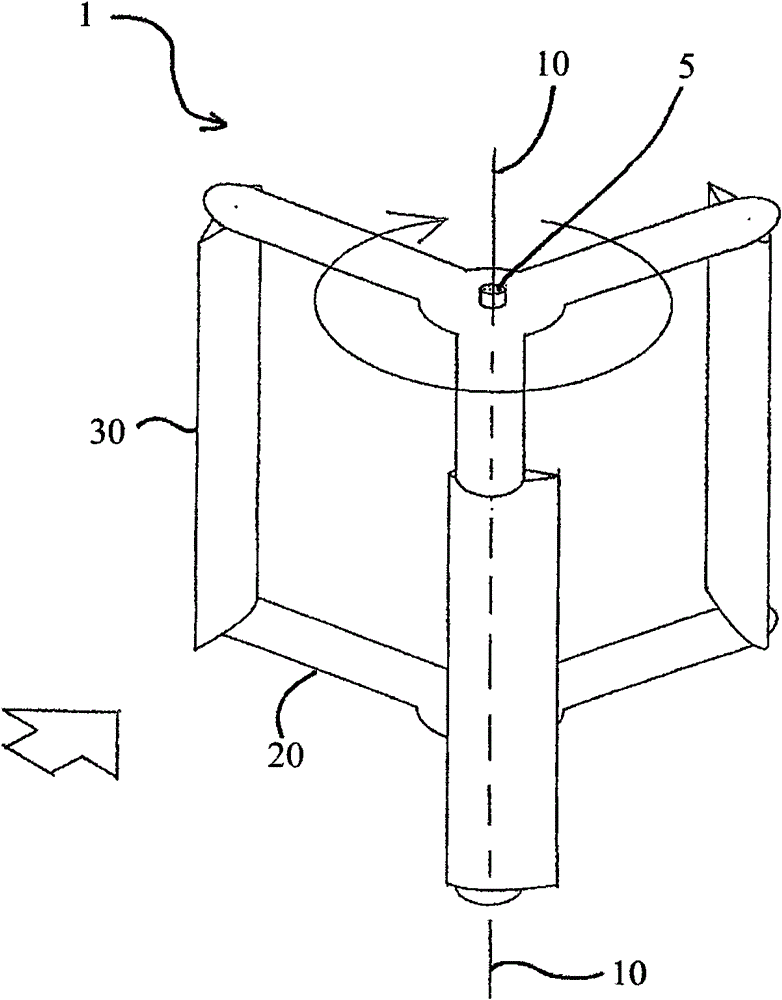
[0088] In one embodiment of the invention, figure 1 A rotating cross-flow power generator 1 suitable for free-flowing fluids such as tidal currents is shown. The generator 1 comprises a shaft 5 with a shaft 10 around which the entire generator rotates during use of the generator. Several upper and lower support arms 20 extend outwardly from the upper and lower ends of the shaft 5 at equally spaced angles. A directional changing vane 30 extends between each set of upper and lower support arms, spaced from the shaft 10 such that the longitudinal axis of the vane is aligned parallel to the rotational shaft 10 . While the illustrated embodiment has three fins 30, in practice there may be any desired number of fins 30 and support arms (upper and lower, or mid-span of). Shaft power from the rotating cross-flow power generator may be transferred to a generator (not shown) by means of a drive train (not shown) or a gearbox (not shown) to generate electrical power, as is known in t...


PUM


Abstract

An airfoil (30) arranged for use in a fluid flow of varying direction relative to the airfoil, has arranged thereon a plural axis hinge (50) for automatic adjustment of the angle of pitch of the airfoil. The airfoil can be applied to a rotary crossflow device for use in a fluid flow of varying apparent flow direction, an oscillating device for use in a fluid flow, a force generation device for use in a fluid flow of varying direction, or a flow control device for use in a fluid flow of alternating direction.

Description

technical field [0001] The invention relates to an airfoil arranged for redirected fluid flow relative to the airfoil. The invention also extends to rotary crossflow devices, oscillating devices, force generating devices and flow control devices. Background technique [0002] There have been several proposals to use rotary cross-flow devices as power generators in free-flowing fluids such as tidal flows, and as propellers or propulsion devices. [0003] Rotating cross-flow devices have an axis of rotation perpendicular to the direction of flow and have been shown to be theoretically more efficient than good rotating axial turbine / propulsion devices. Rotary cross-flow devices have the advantage of being able to cover a large rectangular swept area, and when used as power generators, have the inherent advantage of being a surface-deployable drivetrain. [0004] However, the potential efficiencies of such devices are largely unrealized due to the very complex fluid flow fiel...

Claims


Application Information

Patent Timeline
Patent Type & Authority Patents(China)
IPC IPC(8): F03B17/06
CPCF03B17/062Y02E10/226Y02E10/223F03B17/06Y02E10/28Y02E10/74Y02E10/30Y02E10/20F03B3/12F03D3/0418F03D3/061F05B2240/214F05B2260/79F05B2260/72B63H16/04A63B31/00F03B15/20F03B3/14
Inventor 大卫·劳森
Owner 大卫・劳森
Learn More