Optical member, illuminating device, display, and television receiver

A technology for optical components and lighting devices, which can be applied to cooling/heating devices, lighting devices, and components of lighting devices, etc., and can solve problems such as yellow light, increased weight of diffuser plates, and increased volume.

Inactive Publication Date: 2010-02-17
SHARP KK
View PDF1 Cites 4 Cited by
  • Summary
  • Abstract
  • Description
  • Claims
  • Application Information

AI Technical Summary

Problems solved by technology

That is, the enlargement of the screen size resulted in an increase in the volume of the diffuser plate in order to ensure the corresponding area and rigidity, and a significant increase in the weight of the diffuser plate
[0005] In addition, the diffusing particles contained in the diffusing plate have the property of diffusing more light in the short-wavelength region among the visible light emitted by the light source. Therefore, when the thickness of the diffusing plate is increased, the visible light transmitted through the diffusing plate The light in the mid-to-long wavelength region contains relatively much light, and as a result, there is a problem of being seen as yellowish light

Method used


Image

  • Optical member, illuminating device, display, and television receiver
  • Optical member, illuminating device, display, and television receiver
  • Optical member, illuminating device, display, and television receiver

Examples


Embodiment approach 1

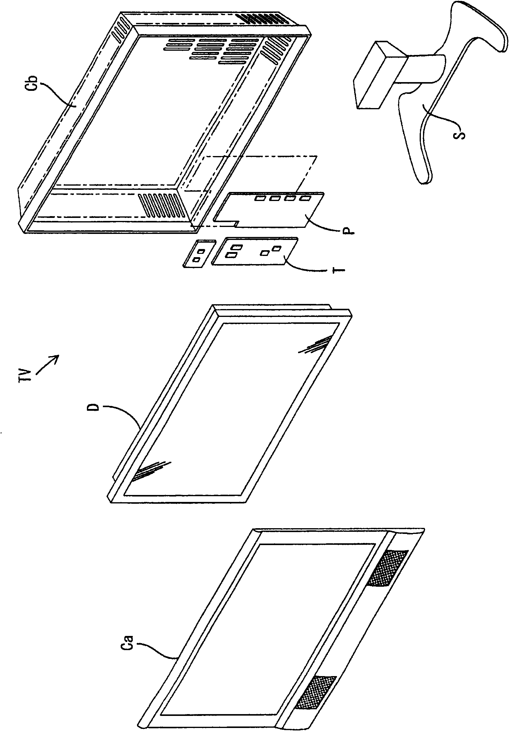
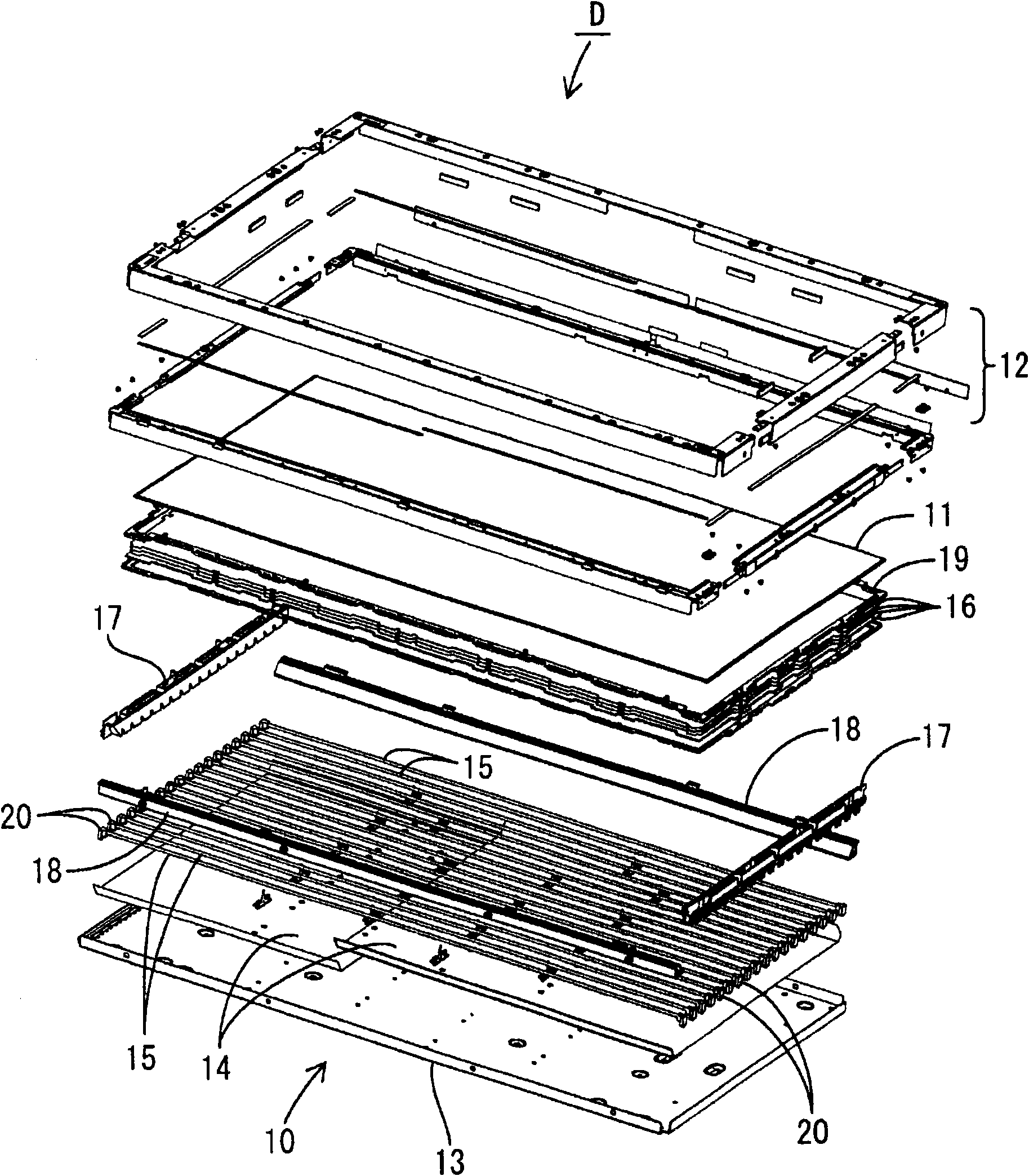
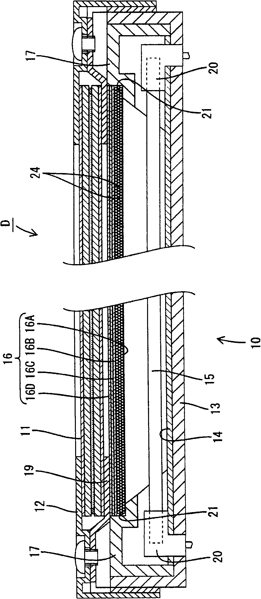
[0063] refer to Figure 1 to Figure 17 , Embodiment 1 of the present invention will be described. In Embodiment 1, a liquid crystal display device D is exemplified as a display device.

[0064] The liquid crystal display device D is made into a horizontally long square as a whole, such as figure 2 As shown, the structure is maintained in an assembled state by the frame 12 of the backlight 10 which is an external light source (illumination device) covering the liquid crystal panel 11 which is a display panel and the liquid crystal panel 11 from the front side. The liquid crystal panel 11 is arranged on the front side of the backlight 10 , and the backlight 10 illuminates the liquid crystal panel 11 from the back side. This liquid crystal display device D can be applied to a television receiver TV. Television receiver TV, such as figure 1 As shown, it is composed of: a liquid crystal display device D; two casings Ca and Cb on the front and back sides that sandwich and accom...

example 1

[0081] Diffuser plate 16A-1 of Example 1, as Figure 8 and Figure 9 As shown, each unit cylindrical body 25-1 ( Figure 8 Shown by double-dashed lines) as a whole is formed into a cylindrical shape with a regular hexagonal cross-section. Furthermore, the cross-sectional shape of the inner peripheral surface of the unit cylindrical body 25-1, that is, the hole portion 24-1 is a regular hexagonal shape. The unit cylindrical body 25-1 is aligned along the long side direction of the substrate 23-1 (plane direction, Figure 8 Shown in the left-right direction) and will be connected to each other, thereby forming a layer, the layer along the thickness direction of the base material 23-1 ( Figure 8 shown in the up and down direction) stack multiple ( Figure 8 Three layers in the middle), thus constituting the base material 23-1.

[0082] The unit cylindrical bodies 25-1 arranged in the thickness direction of the base material 23-1 are arranged to be shifted in the longitudina...

example 2

[0086] Diffuser plate 16A-2 of Example 2, as Figure 10 As shown, each unit cylindrical body 25-2 ( Figure 10 The shape shown by the two-dot chain line) is the same as the above-mentioned example 1, which is a cross-sectional regular hexagonal shape, but its orientation is changed to the orientation of the unit cylindrical body of example 1 rotated 90 degrees.

[0087] The unit cylindrical body 25-2 is formed to include a unit cylindrical body parallel to the plate surface of the base material 23-2 at the edge (one side of the inner peripheral surface) of the hole portion 24-2. In other words, the hole 24 - 1 shown in Example 1 is oriented in a direction in which the regular hexagon is erected, whereas the hole 24 - 2 shown in Example 2 is oriented in a direction in which the regular hexagon is lying down. In addition, the description of the same structure (arrangement) or operation as the above-mentioned example 1 is omitted.

[0088] In this way, after the unit cylindrica...


PUM


Abstract

The present invention provides an optical member, an illuminating device, a display, and a television receiver. A diffusion plate (16A) comprises a light-permeable plate-like base (23). The base (23) is formed by arranging unit cylindrical bodies (25) each having a hole part (24) in the surface and thickness directions of the base (23) and connecting them to each other. The unit cylindrical bodies (25) arranged in the thickness direction of the base (23) are disposed at positions deviated from each other in the surface direction of the base (23). The intermediate position between the unit cylindrical bodies (25) arranged in the surface direction and the center position of the unit cylindrical bodies (25) arranged in the thickness direction relative to the unit cylindrical bodies (25) arranged in the surface direction coincide with each other, and the cross sectional shape of the hole part (24) is a regular hexagon. Namely, the base (23) is formed in a honeycomb structure.

Description

technical field [0001] The present invention relates to optical components, lighting devices, display devices and television receivers. Background technique [0002] A liquid crystal display device is composed of a liquid crystal panel and a backlight provided on the rear side of the liquid crystal panel. Among them, the backlight includes: a base for accommodating light sources such as cold cathode tubes and having an opening on the light emitting side; [0003] The optical component includes a diffusion plate in which a large number of diffusion particles are dispersed in a transparent plate-shaped base material, and a thin diffusion sheet, a lens sheet, and a brightness enhancement sheet are sequentially laminated on the diffusion plate. Since the diffusion plate has a function of supporting the sheets laminated thereon, a certain degree of rigidity is required. Moreover, as an example of a diffuser plate, the diffuser plate described in the following patent document 1 ...

Claims


Application Information

Patent Timeline
Patent Type & Authority Applications(China)
IPC IPC(8): G02B5/02F21S2/00F21V3/00F21V29/00G02F1/13357F21Y103/00
CPCG02B5/0278G02F2001/133628G02F1/133606G02B5/0247G02B5/0257G02F1/133628
Inventor 黑水泰守
Owner SHARP KK
Why Eureka
Try Eureka