Special edge planer for steel band

A technology of edge planing machine and steel strip, applied in the direction of planer groove machine, planer/slotting machine, metal processing equipment, etc., can solve the problems of not meeting production needs, a large number of chamfering equipment and manpower, etc., to achieve a high degree of automation, saving Production cost, the effect of simplifying the process flow

Inactive Publication Date: 2010-02-24
JIANGSU CCVI BEARING
View PDF0 Cites 4 Cited by
  • Summary
  • Abstract
  • Description
  • Claims
  • Application Information

AI Technical Summary

Problems solved by technology

[0002] Sliding bearings are generally made of copper-based, tin-based, lead-based, iron-based, Babbitt alloy, oil-containing powder metallurgy, graphite-based, graphite-copper-based, pure resin-based, synthetic resin, multi-layer composite (steel back + copper +PTFE three-layer composite), metal base spraying type, metal base lamination type, metal base impregnation type, polymer resin base type, steel back bronze sintered type (JF-800 bimetallic), the tradition of making shaft sleeves with these materials The ordinary process is to first divide the strip material into strips, then punch and cut, roll, shape, chamfer, and finally become parts such as bushings, bushings, thrust washers, etc., to produce sliding bushings, especially small-sized bushings. Traditionally, After shaping, use a chamfering machine to chamfer the inner and outer corners and end faces. The output of a shift is 2000-3000 sets, which requires a lot of chamfering equipment and manpower, and cannot meet the production needs.

Method used


Image

  • Special edge planer for steel band
  • Special edge planer for steel band
  • Special edge planer for steel band

Examples


Embodiment Construction

[0016] The technical solutions of the present invention will be described in detail below in conjunction with the accompanying drawings.

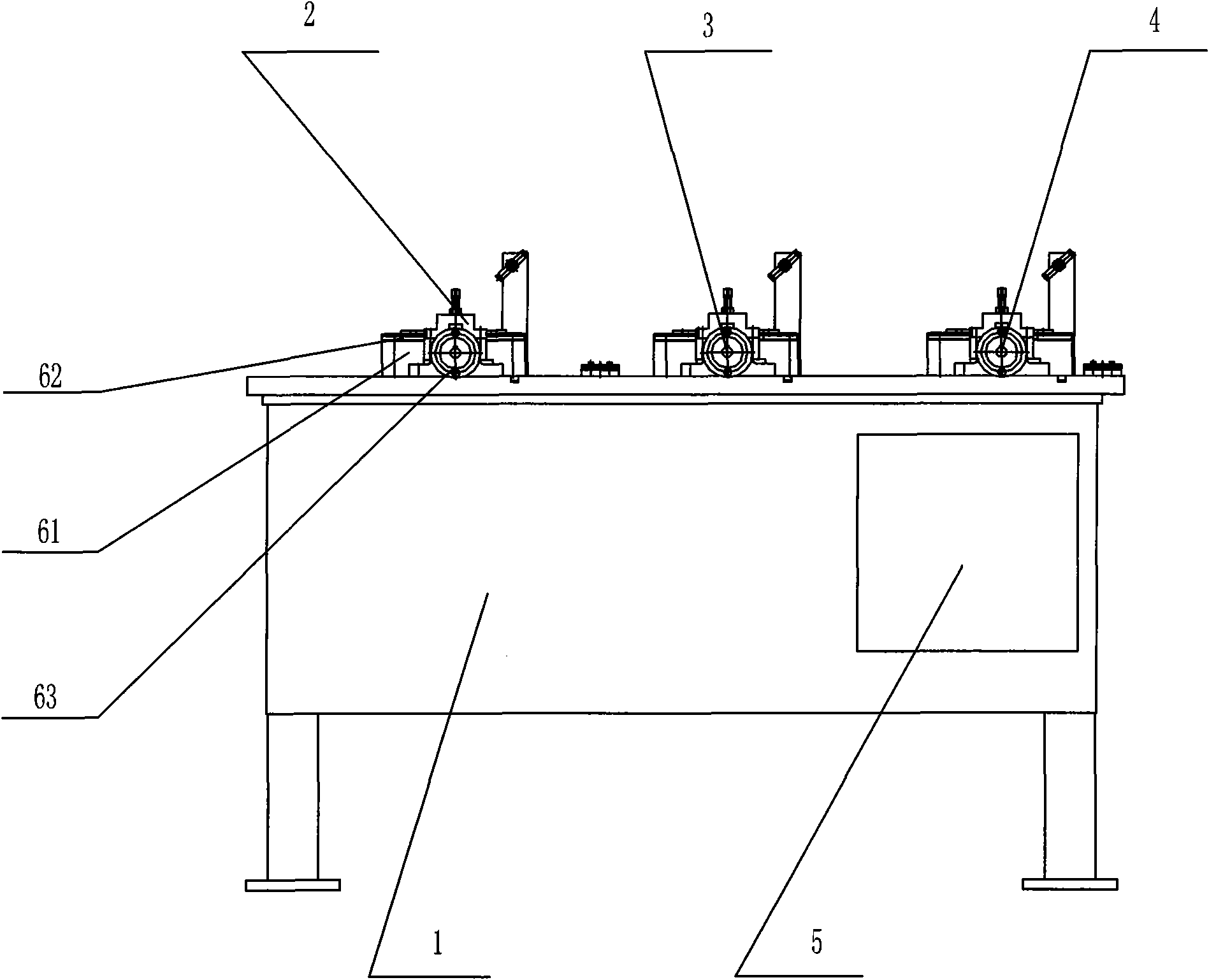
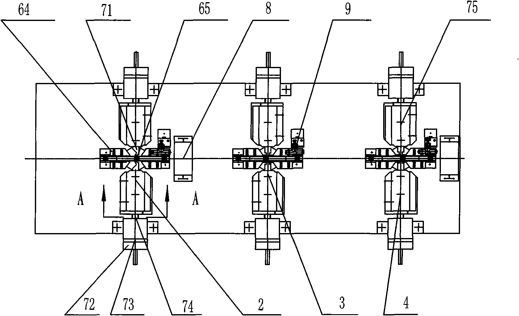
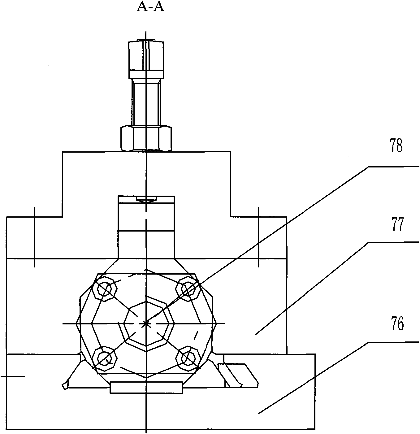
[0017] Such as Figures 1 to 3 As shown, the edge planer for steel strips according to the present invention includes a body 1 and a workbench arranged on the body 1, on which the bottom chamfering planing device 2, End face planing device 3 and upper chamfering planing device 4 .

[0018] Described lower chamfering planing device 2, end face planing device 3 and upper chamfering planing device 4 are basically the same in structure, but the tool needs to be installed according to the processing procedure requirements it carries out, the lower chamfering planing device 2, The end face planing device 3 and the upper chamfering planing device 2 all include a guide clamping mechanism and two symmetrically arranged cutter feed mechanisms respectively, and the guide clamp mechanism is located in the middle of the two cutter feed mechanisms, and ...


PUM


Abstract

The invention relates to a special edge planer for a steel band, comprising a planer body and a work bench arranged on the planer body, wherein the work bench is installed with a lower chamfer planning device, an end face planning device and an upper chamfer planning device in sequence according to the conveying direction of the steel band. Therefore, the invention can carry out lower chamfer planning, end face planning and upper chamfer planning on shaped steel band in sequence, does not need to process by utilizing a plurality of chamfer machines like in the prior art, simplifies the processflow of steel band planning, facilitates the whole machining process to be integrated, and has high degree of automation, thereby effectively improving the work efficiency of steel band planning andsaving production cost.

Description

technical field [0001] The invention relates to an edge planer, in particular to a special edge planer for steel strips. Background technique [0002] Sliding bearings are generally made of copper-based, tin-based, lead-based, iron-based, Babbitt alloy, oil-containing powder metallurgy, graphite-based, graphite-copper-based, pure resin-based, synthetic resin, multi-layer composite (steel back + copper +PTFE three-layer composite), metal base spraying type, metal base lamination type, metal base impregnation type, polymer resin base type, steel back bronze sintered type (JF-800 bimetallic), the tradition of making shaft sleeves with these materials The ordinary process is to first divide the strip material into strips, then punch and cut, roll, shape, chamfer, and finally become parts such as bushings, bushings, thrust washers, etc., to produce sliding bushings, especially small-sized bushings. Traditionally, After shaping, use a chamfering machine to chamfer the inner and o...

Claims


Application Information

Patent Timeline
Patent Type & Authority Applications(China)
IPC IPC(8): B23D1/26B23D7/00
Inventor 王军寿印德峰姜玉红
Owner JIANGSU CCVI BEARING
Why Eureka
Try Eureka