Error compensation method of numerical control grinding contour of camshaft

A technology of contour error and compensation method, which is applied in the field of error compensation, can solve the problems of affecting application, imperfect compensation of cam contour error, and inability to comprehensively consider the comprehensive influence, etc.

Inactive Publication Date: 2010-02-24
HUNAN UNIV
View PDF0 Cites 29 Cited by
  • Summary
  • Abstract
  • Description
  • Claims
  • Application Information

AI Technical Summary

Problems solved by technology

Since the actual processed cam profile is the result of a combination of various factors, the method of modeling the individual error influencing factors has great limitations; the second is to establish a mathematical model of each moving part of the machine tool based on the kinematics theory of the multi-body system , deduce the constraint equations and parameters of precision motion, and finally generate precision numerical control inst

Method used


Image

  • Error compensation method of numerical control grinding contour of camshaft
  • Error compensation method of numerical control grinding contour of camshaft
  • Error compensation method of numerical control grinding contour of camshaft

Examples


Embodiment 1

[0057] (1) Trial cutting processing

[0058] Before performing trial cutting and measurement on the cam plate, clean the camshaft first, and place the workpiece for a short period of time as much as possible before measuring. During the measurement, multiple measurements are made on each cam piece to obtain multiple sets of measured lift data. The lift error values ​​of several sets of data are calculated by formula (a), and the transformation trend of several sets of errors is observed. If the change trends of several groups of errors are basically consistent on the whole, it means that the detection state of the camshaft is relatively stable, and the actual contour detected at this time is also relatively accurate.

[0059] e=h S -h L (a)

[0060] In the formula: e-lift error

[0061] h S - measured lift

[0062] h L -Theoretical lift

[0063] After m times of trial cutting, each cam piece will produce m sets of measured lift and lift error. The arithmetic mean...

Embodiment 2

[0105] (1) Trial cutting process to obtain lift error

[0106] In this embodiment, the trial cutting process of a camshaft part is carried out on a fully numerically controlled camshaft grinder, and the maximum allowable lift error of the part is 0.020 mm. Because the grinding machine has been fully debugged and preheated before processing, and the running state is stable, it is enough to try cutting once. The obtained lift error is as Figure 4 As shown, the maximum lift error of the camshaft is at a rotation angle of 99°, and the error value is -0.021mm, which does not meet the accuracy requirements

[0107] (2) Analyze the law of lift error and obtain prediction error

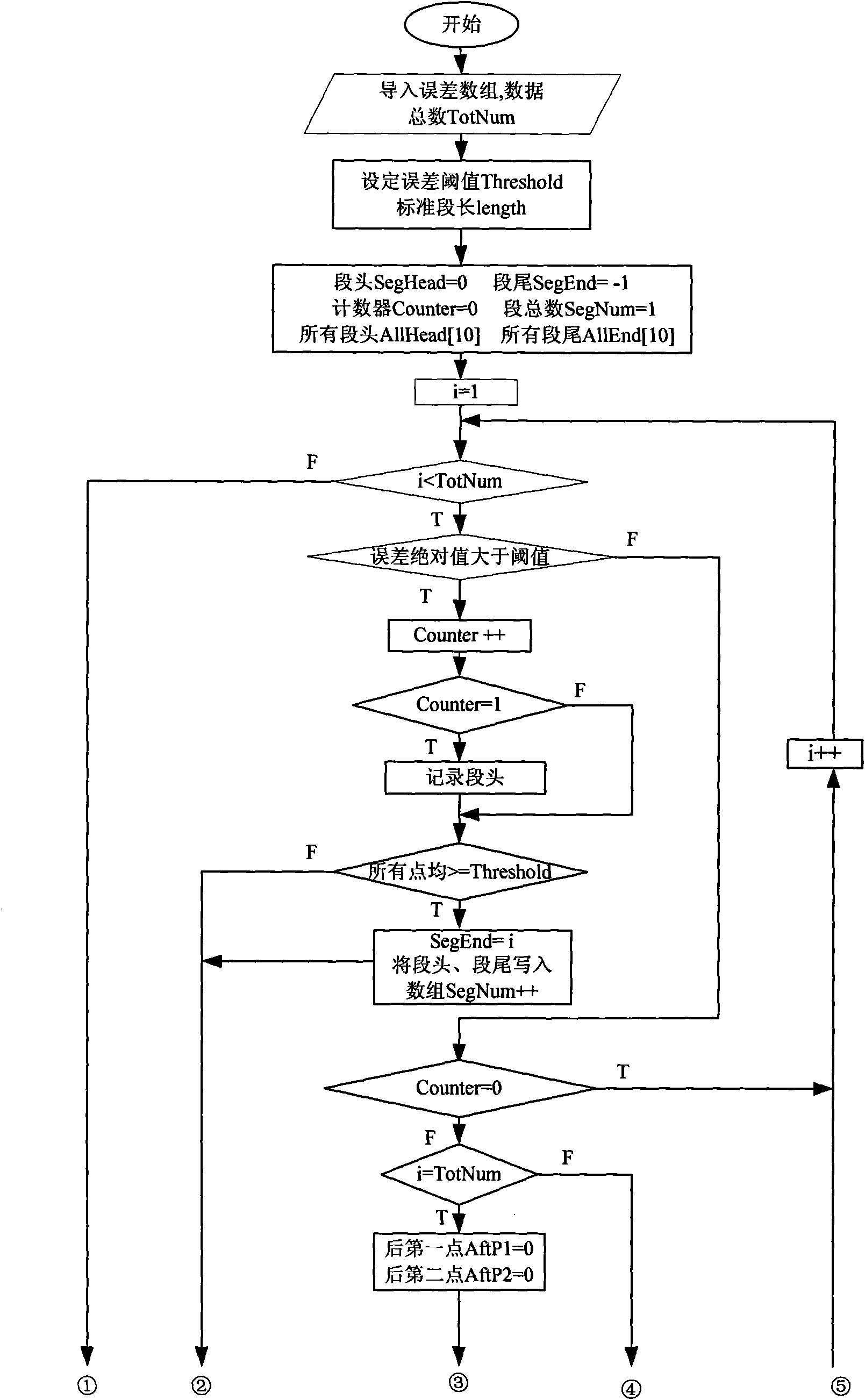
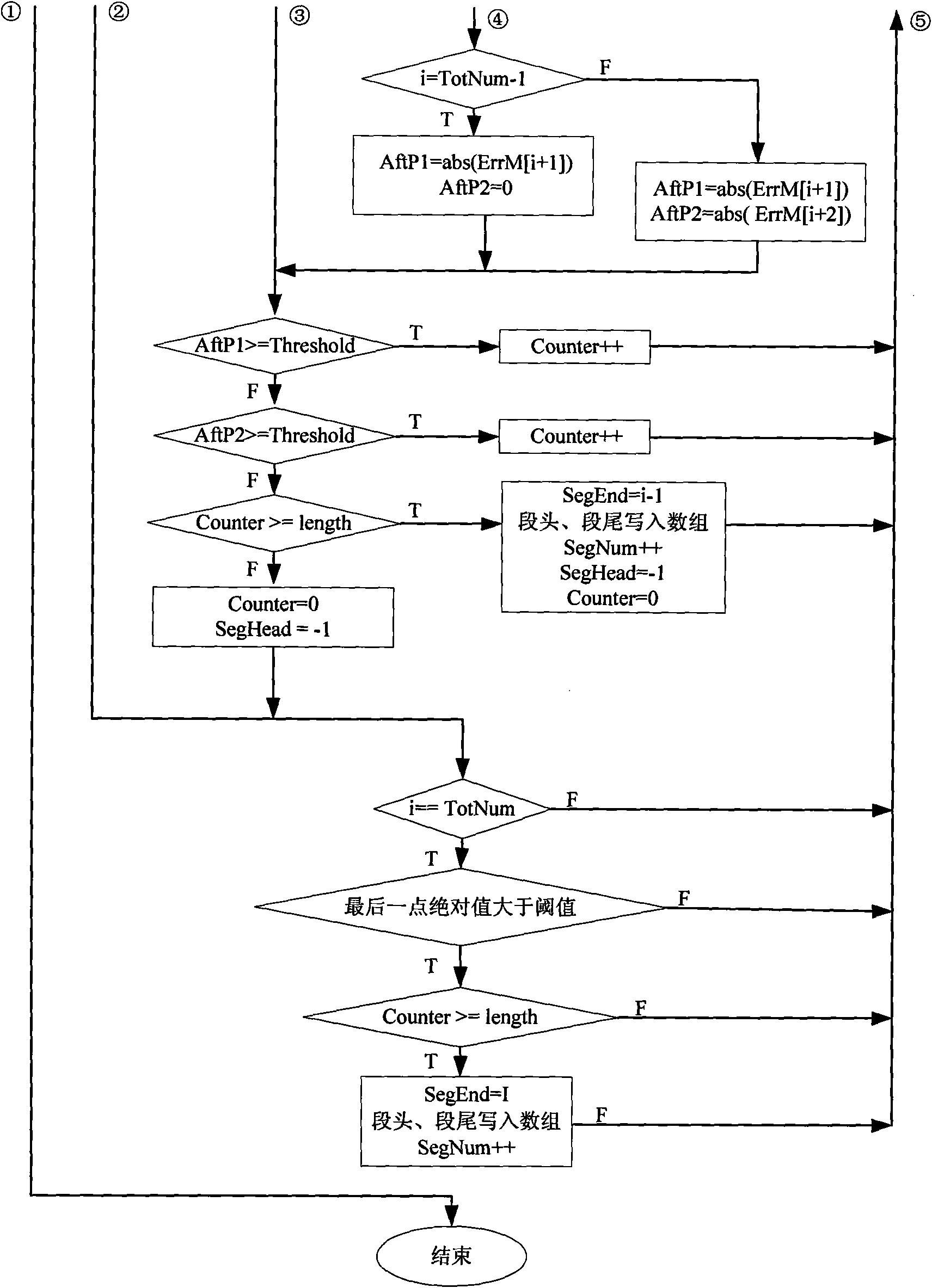
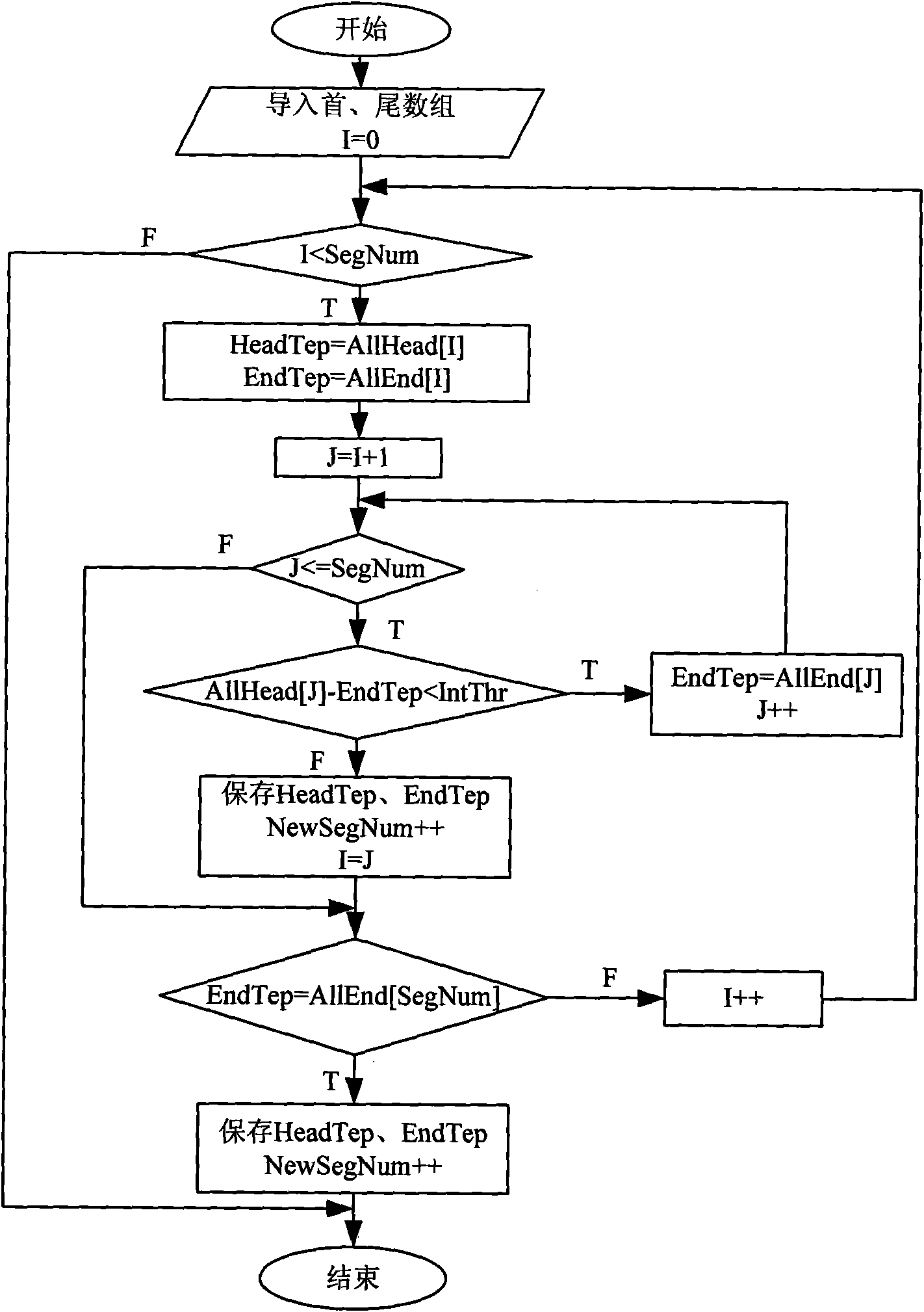
[0108] The lift error curve is analyzed by the error analysis software to realize the identification and merging of regular segments, and the least square method polynomial fitting is performed on the lift error curve. In this embodiment, the identification threshold of the error rule segment is set to 0....


PUM


Abstract

The invention discloses an error compensation method of numerical control grinding contour of a camshaft, comprising the following steps: a. performing offline measurement on the contour line of a processed cam sheet by multiple trail cut processing to obtain practical contour line data for respectively lifting; b. calculating the lifting error value of one circle of the whole cam sheet by comparing theory lift and actual measurement lift data, analyzing the lift error, and predicting the error; c. building a virtual lift table, and performing secondary fairing processing to the virtual lift;d. adopting a post-processed virtual lift table to replace an original lift table, and performing numerical control processing of the camshaft which has the same type with a trail cut camshaft under the same technological condition. Based on the above steps, the invention programs and develops the error analysis and compensation processing software of numerical control grinding contour error of acamshaft and realizes the intelligent and automatic application of a technical method; the lift error value of the whole contour line of the processed cam sheet is integrally reduced, molded line precision is obviously improved, no burn or waveness exists on the surface of the contour, surface quality is favorable, and error compensation effect is obvious.

Description

technical field [0001] The invention relates to an error compensation method, in particular to a contour error compensation method in the numerical control grinding process of a camshaft. Background technique [0002] The camshaft is one of the main parts of the engine. It is used to control the intake and exhaust of the engine. The accuracy of its profile is extremely critical to the performance of the engine. The machining quality and efficiency of the camshaft directly affect the quality and quality of automotive products. Development of the automobile industry. Machining accuracy is one of the most important technical indicators of camshaft grinding. The main methods to improve machining accuracy are: error prevention and error compensation. Error prevention is to achieve high-precision machining by improving the accuracy of machine tool hardware. This method is expensive and uneconomical, and it is difficult to improve the machining accuracy after reaching a certain le...

Claims


Application Information

Patent Timeline
IPC IPC(8): B24B19/12
Inventor 邓朝晖曹德芳万林林张晓红
Owner HUNAN UNIV
Why Eureka
Try Eureka