
Method for treating landslide and slide slope hazards

A landslide mass and sliding surface technology, applied in the field of geological disaster control measures, can solve the problems of exacerbation, hardship and danger, and difficulty of anti-sliding piles, so as to achieve strong compressive performance and overcome hardship and danger. Effect

Inactive Publication Date: 2011-05-11
NORTHWEST RES INST CO LTD OF C R E C
View PDF0 Cites 2 Cited by
  • Summary
  • Abstract
  • Description
  • Claims
  • Application Information

AI Technical Summary

Problems solved by technology

[0003] 1) It is very difficult to set up anti-slide piles for landslide bodies with large landslide thrust and large sliding surface depth
[0004] 2) For the construction of conventional anti-sliding structures, it is necessary to excavate underground on the landslide body into the bearing layer of the sliding bed to build supporting structures. In the active landslide body, large-depth pile wells are excavated by blasting (sometimes the pile well is as deep as 70 meters), and reinforced concrete construction, drilling rig drilling and anchor cable construction are required in the pile well, because these constructions are all manually operated in the pile well. Its construction is extremely difficult, dangerous and arduous, and accidents of personal injury and death are extremely likely to occur during construction.
At the same time, due to the instability of the landslide itself, this instability will be further aggravated during related construction, and disasters will easily occur during construction.
[0005] 3) Conventional anti-sliding structures such as anti-sliding piles and anchor cable frames (ground beams) consume a lot of materials and are expensive
[0006] 4) The materials of conventional anti-slip structures do not work under the most reasonable stress mode, and cannot effectively exert the mechanical properties of the materials
For example, the pile body of the anti-slide pile is subject to the action of bending moment and shear force, which is prone to failure and damage.

Method used


Image

  • Method for treating landslide and slide slope hazards
  • Method for treating landslide and slide slope hazards
  • Method for treating landslide and slide slope hazards

Examples


Embodiment Construction

[0029] The following is an embodiment of the present invention.

[0030] 1. Analysis and calculation of original data and cables

[0031] Raw data:

[0032] Landslide thrust (6m) = 2154t

[0033] Single width thrust = 359t

[0034] Depth of sliding surface: H=44m

[0035] Calculation distance: D=6m

[0036] Thrust distribution coefficient: K=2.225207

[0037] Upper cable tension: P0=528t

[0038] Upper cable inclination: α=23°

[0039] (Note: The tension of the upper cable and the inclination angle of the upper cable are obtained by adjusting the shape of the cable)

[0040] 2. Mathematical and mechanical analysis of cables

[0041] a. Cable equation

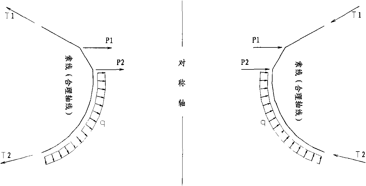
[0042] ∫ 0 y 0 f ( y ) ( y - y 0 ) dy = py cos α + ...


PUM


Abstract

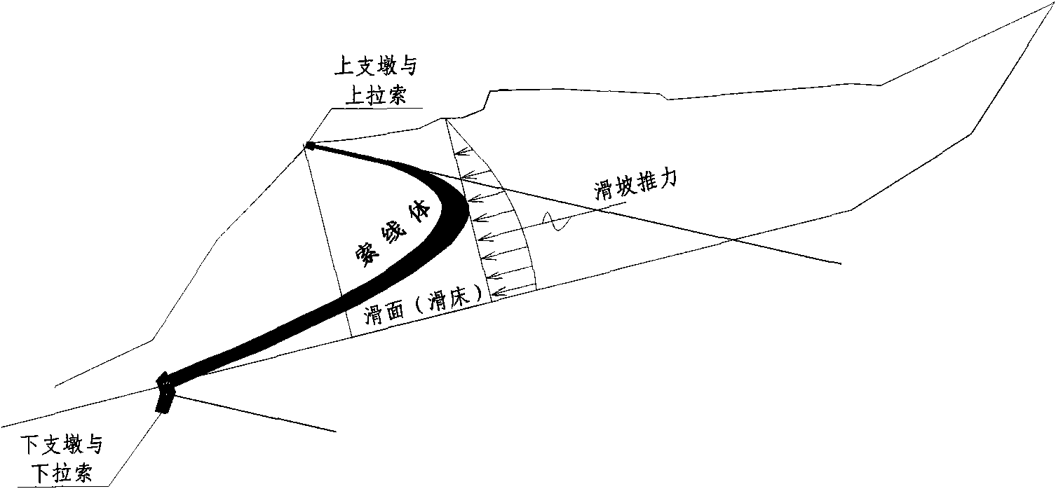
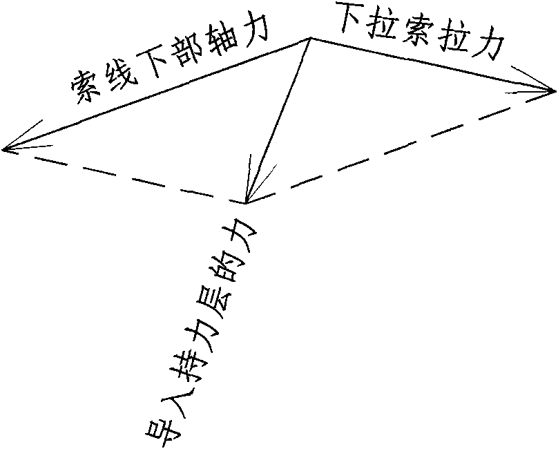
The invention discloses a technical scheme for treating geologic hazards of a landslide, a side slope and the like, which is as follows: according to the design requirement, lower buttress piers are arranged below the crossed part of a lower slope toe and a sliding surface at intervals, upper buttress piers are arranged above the sliding surface corresponding to various lower buttress piers, guy cables are respectively arranged on the upper buttress piers and the lower buttress piers and a guy cable body which is similar to a catenary and made of elastic material is arranged in a slide slope body between the upper buttress piers and the lower buttress piers which mutually correspond, wherein the protruded part of the guy cable body points to the thrust direction of the slide slope. The distances among the guy cables meet the stable conditions of the slide slope body between two adjacent guy cables. In the method, the planes on which the guy cable bodies are positioned are preferably vertical with the water surface curve, but the included angle which is within 90+ / -8 degrees between the planes of the guy cable bodies and the water level can be permitted according to different geological conditions.

Description

technical field [0001] The invention relates to control measures for geological disasters such as landslides and side slopes. Background technique [0002] Landslide is a common geological disaster, in order to prevent its destruction, engineering measures must be taken to control it. The commonly used measures for landslide or slope treatment are anti-slide piles or anchor cable frames (ground beams). But prior art has following deficiency: [0003] 1) It is very difficult to set up anti-slide piles for landslide bodies with large landslide thrust and large depth of sliding surface. [0004] 2) For the construction of conventional anti-sliding structures, it is necessary to excavate underground on the landslide body into the bearing layer of the sliding bed to build supporting structures. In the active landslide body, large-depth pile wells are excavated by blasting (sometimes the pile well is as deep as 70 meters), and reinforced concrete construction, drilling rig dril...

Claims


Application Information

Patent Timeline
Patent Type & Authority Patents(China)
IPC IPC(8): E02D17/20
Inventor 刘振明
Owner NORTHWEST RES INST CO LTD OF C R E C
Learn More