Method for protecting power amplifier and protective circuit

A power amplifier and protection circuit technology, which is applied in the field of current limiting protection power amplifiers, can solve the problems of long consumption time, power amplifier burnout, and short response time, and achieve the effects of avoiding burnout, protecting the power amplifier, and short response time

Active Publication Date: 2010-02-24
BOOMSENSE TECH
View PDF2 Cites 17 Cited by
  • Summary
  • Abstract
  • Description
  • Claims
  • Application Information

AI Technical Summary

Problems solved by technology

Due to the extremely short response time of equipment self-excitation, port mismatch, increase of input power, etc., ALC control consumes too long time through complex conversion, and its response speed cannot meet the requirements of protecting the power amplifier, so it is difficult to be effective protection of the power amplifier
[0009] 2. This technology can play a role in many cases, effectively reducing the link gain of the amplifier so that the link output does not exceed the rated power. Long, this method can not achieve the purpose of protecting the power amplifier, or it will burn out the power amplifier
And the above-mentioned patent application does not disclose the technical features to solve the defects of the above-mentioned ALC technology

Method used


Image

  • Method for protecting power amplifier and protective circuit
  • Method for protecting power amplifier and protective circuit
  • Method for protecting power amplifier and protective circuit

Examples


Embodiment 1

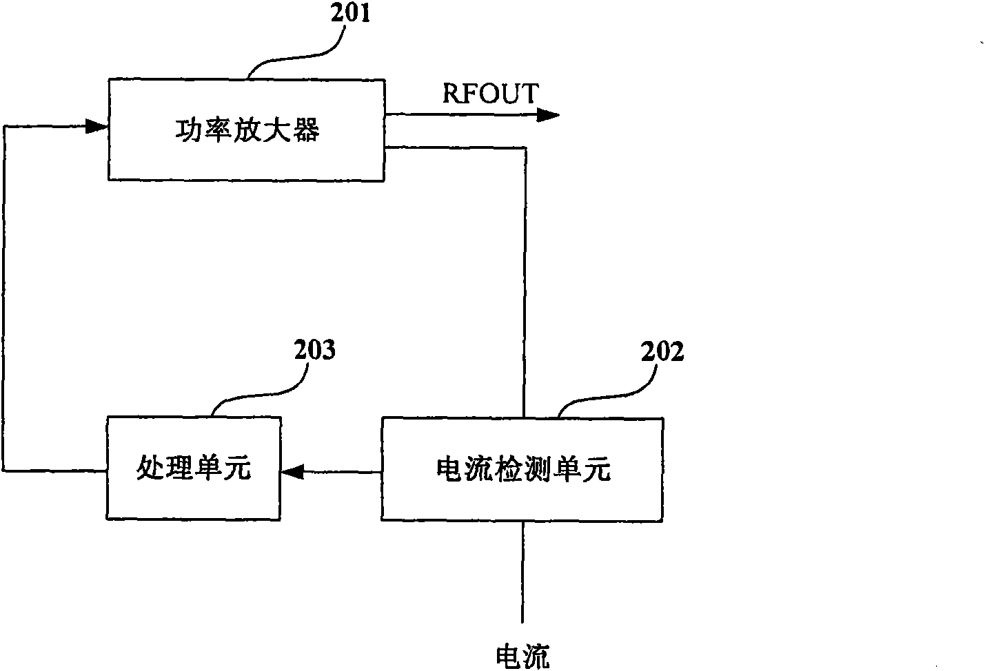
[0029] The present invention provides a protection circuit, such as figure 2 As shown, the circuit includes:

[0030] A current detection unit 202, configured to detect the working current value of the power amplifier 201;

[0031] The processing unit 203 is used to determine whether the operating current value exceeds a preset value, and if the determination result of the processing unit 203 is yes, then reduce or turn off the bias voltage of the power amplifier 201, thereby reducing or turning off the power amplifier Working current to protect the power amplifier from being burned by high current breakdown.

[0032] In this embodiment, when the judgment result of the processing unit 203 is yes, the output voltage value of the processing unit 203 directly reduces or turns off the bias voltage of the power amplifier, wherein, when the judgment result is yes, the output voltage When the value decreases, the bias voltage also decreases. When the voltage value output by the pr...

Embodiment 2

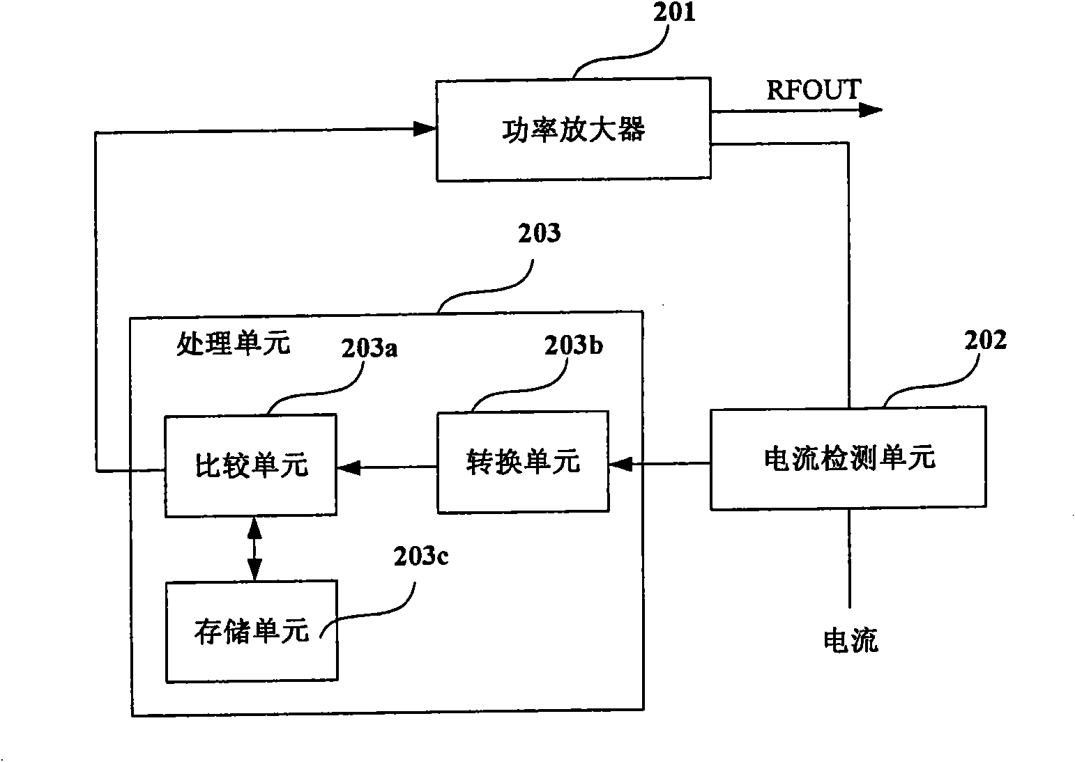
[0036] The present invention also provides a protection circuit, such as image 3 As shown, the protection circuit includes a current detection unit 202 and a processing unit 203; wherein, the function of the current detection unit 202 is consistent with that in Embodiment 1, and will not be repeated here.

[0037] Such as image 3As shown, in this embodiment, the processing unit 203 can determine whether the operating current value exceeds a preset value in the following manner: determine whether the detected voltage value corresponding to the operating current value exceeds a preset voltage value.

[0038] Thus, in this embodiment, the processing unit 203 may include a conversion unit 203b, a comparison unit 203a, and a storage unit 203c; wherein,

[0039] The conversion unit 203b is used to convert the operating current into a corresponding voltage value; in this embodiment, the operating current value is converted into a corresponding voltage value;

[0040] The comparis...

Embodiment 3

[0047] The present invention also provides a protection circuit, such as Figure 4 As shown, the protection circuit includes a current detection unit 202 and a processing unit 203; wherein, the functions of the current detection unit 202 and the processing unit 203 are consistent with those in Embodiment 2, and will not be repeated here.

[0048] Such as Figure 4 As shown, the protection circuit also includes an ALC control unit, and the ALC control unit includes a processing unit 205 and a voltage-controlled attenuator 206, wherein,

[0049] The processing unit 205, when the judgment result of the comparison unit 203a is negative, the processing unit 205 is used to convert the signal strength of the output power of the power amplifier 201 into a signal strength voltage, and compare the converted signal strength voltage with the preset The voltage value of the rated output power is compared, if the received signal strength voltage is higher than the preset voltage value, the...


PUM


Abstract

The invention provides a method for protecting a power amplifier and a protective circuit. The method comprises the following steps: detecting the working current value of the power amplifier; judgingwhether the working current value exceeds a preset value; and if the working current value exceeds the preset value, reducing or turning off the bias voltage of the power amplifier so as to reduce orturn off the working current of the power amplifier. The method adopts a current limiting mode for protecting the power amplifier, reduces the working current of the power amplifier or turns off theworking current of the power amplifier by directly controlling the bias voltage of the power amplifier to prevent the power amplifier from being burnt out by heavy current. The method has an extremelyshort response time and can perform the most effective control in the shortest time and under the worst environment so as to achieve the aim of protecting the power amplifier.

Description

technical field [0001] The present invention relates to the technology of protecting power amplifiers, in particular to the technology of current limiting protection of power amplifiers, in particular to a method and protection circuit for protecting power amplifiers. Background technique [0002] With the development of mobile communication, each operator requires deep network coverage, repeater has become an important equipment in wireless network coverage, so higher requirements are put forward for the management and maintenance of repeater. [0003] At present, in various repeaters, the power amplifier is often damaged. These damages are mainly caused by self-excitation of equipment, port mismatch, excessive input, unreasonable engineering design, operation errors and other reasons. The working current of the power amplifier becomes large and burns out. Especially for some high-gain repeaters such as wireless repeaters and frequency-shifting repeaters, the damage of the...

Claims


Application Information

Patent Timeline
Patent Type & Authority Applications(China)
IPC IPC(8): H03F1/52
Inventor 张庆文万文定
Owner BOOMSENSE TECH
Why Eureka
Try Eureka