
Method of charging double electric layer electrochemical capacitors

A technology of electrochemistry and charging process, applied in current collectors, battery circuit devices, electric vehicles, etc., can solve problems such as unsolved practical tasks, and achieve the effect of loss compensation

Inactive Publication Date: 2010-02-24
UNIVERSAL SUPERCAPACITORS LLC
View PDF4 Cites 3 Cited by
  • Summary
  • Abstract
  • Description
  • Claims
  • Application Information

AI Technical Summary

Problems solved by technology

However, the practical task of controlling the charging process of HES remains unsolved

Method used

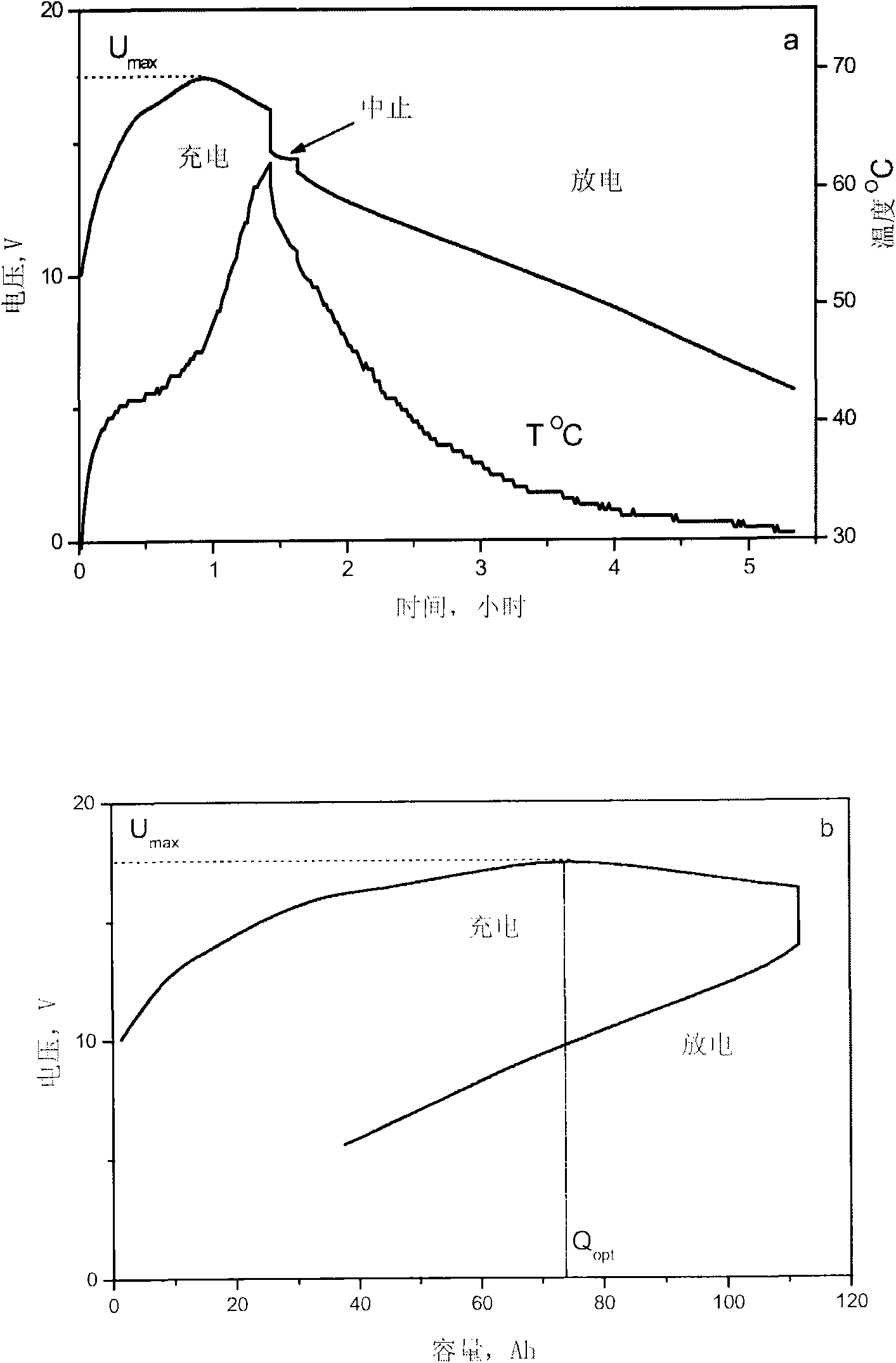
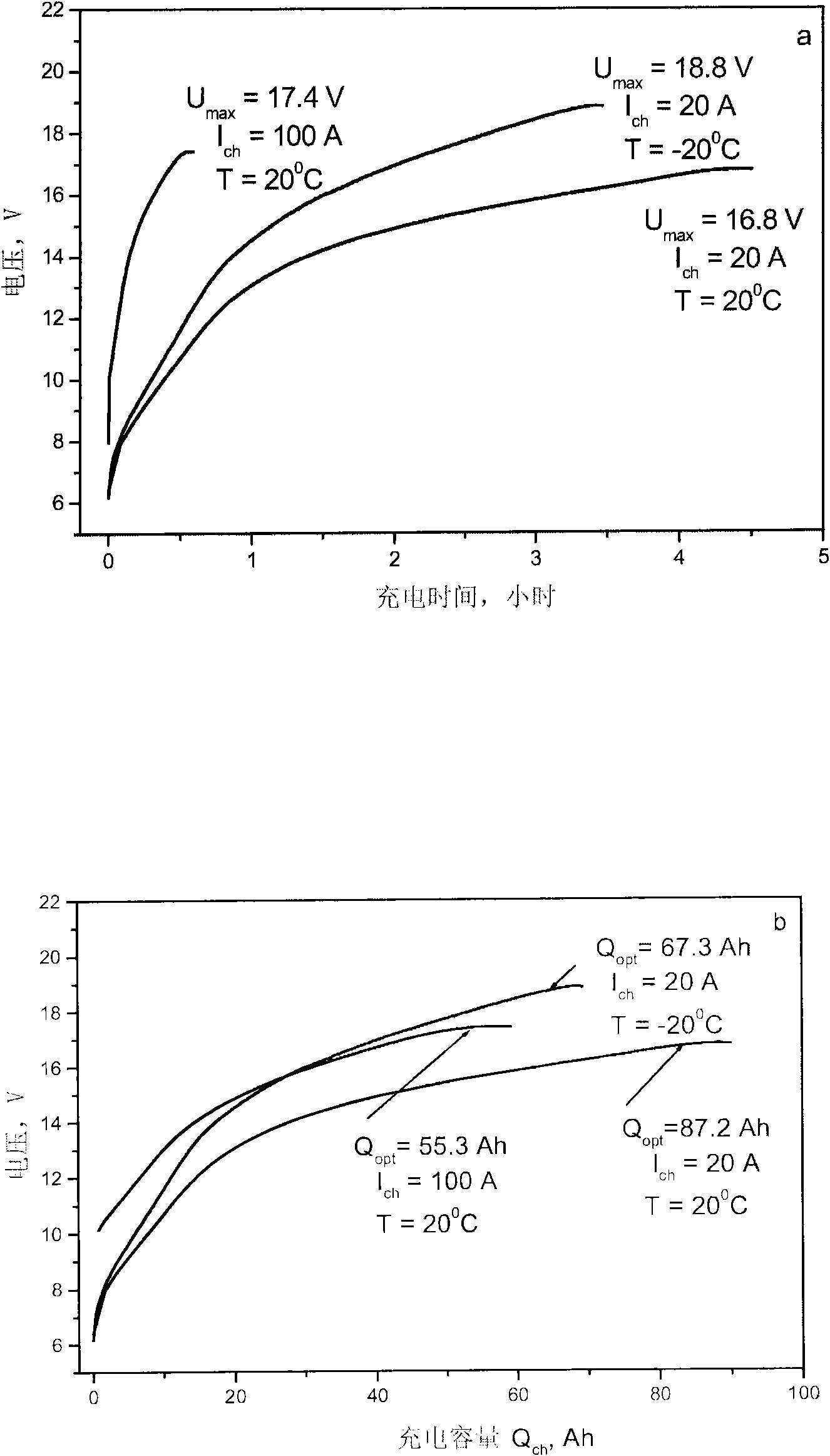
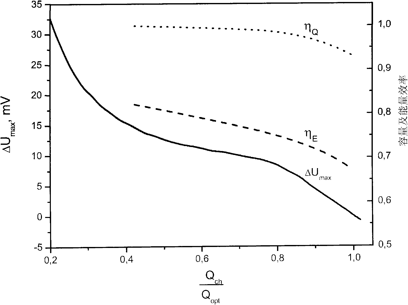

Image

  • Method of charging double electric layer electrochemical capacitors
  • Method of charging double electric layer electrochemical capacitors
  • Method of charging double electric layer electrochemical capacitors

Examples


Embodiment Construction

[0057] Detailed descriptions of several specific but exemplary embodiments of the invention are provided below.

[0058] Example 1

[0059] consists of seven series connected P b o 2 |H 2 SO 4 The capacitor module composed of the HES of the |C system is charged. The parameters of a single HES observed at room temperature during charging at a constant current of 50 A in the voltage window of 2.4–0.8 V are:

[0060] Capacitance 180kF

[0061] Coulomb capacity 62Ah

[0062] Transmitted energy 110Wh

[0063] Impedance (at 50Hz frequency) 1.2mOhm

[0064] Self-discharge current 50mA

[0065] figure 1 The voltage and temperature changes of the capacitor module during charging and discharging at a constant current of 50 A in ambient air at room temperature are shown. As shown, the state of charge increases until the charge voltage reaches a maximum value of U max = 16.8V, then it starts to decrease as charging continues.

[0066] Such as figure 2 As shown in , the vo...


PUM


Abstract

The present invention is directed to methods for the automatic charging of an electrochemical electrical energy storage device. Charging may be performed until a pre-assigned voltage increment value measured across the terminals of the storage device is reached. Recurrent periods of charging and rest may be employed, with measurements of voltage taken and voltage increment determined after the passage of an assigned quantity of electrical energy. Automatic completion of the charging process is provided for, irrespective of the design features and number of energy storage devices (e.g., capacitors) in a module, the initial state of charge and / or temperature of the storage device, or the value and / or time instability of the charging current.

Description

Background of the invention [0001] The present invention relates to the charging of electrochemical capacitors designed to store electrical energy. More specifically, the present invention aims at providing an efficient method for charging electrochemical capacitors when the charging power changes from time to time, and at ensuring timely completion of the charging process once the optimal state of charge is reached. [0002] Heterogeneous electrochemical supercapacitor (HES) energy storage devices have been increasingly used for electrical energy storage (see, eg, US Patent 6,518,734 to A. Nourai et al., entitled "System And Method Of Forming Capacitor-Based Electrical Energy Storage Modules"). Traditionally, electrical energy storage for rechargeable power sources has been dominated by batteries. However, various features of HES devices make them superior to batteries for electrical energy storage. For example, while HES devices are inferior to batteries in terms of their ...

Claims


Application Information

Patent Timeline
Patent Type & Authority Applications(China)
IPC IPC(8): H02J7/00
CPCY02E60/13
Inventor N·F·斯塔罗杜布采夫V·A·卡尔波夫V·A·德罗诺夫S·A·卡扎良V·I·科甘J·R·米勒S·N·拉祖莫夫A·I·斯梅尔科夫S·V·科特维年科
Owner UNIVERSAL SUPERCAPACITORS LLC
Learn More