
Universal data acquisition unit

A technology for collecting devices and general data, applied in general control systems, instruments, computer control, etc., can solve the problems of low level of intelligence, unusable use, increased investment, etc., to improve the level of intelligence, facilitate supporting use, The effect of high co-analog ratio

Inactive Publication Date: 2012-05-09
NORTHEASTERN UNIV LIAONING
View PDF5 Cites 0 Cited by
  • Summary
  • Abstract
  • Description
  • Claims
  • Application Information

AI Technical Summary

Problems solved by technology

[0003] (1) The accuracy of data acquisition is not high, the signal collected by the transmitter has not been processed by fine filtering, and the interference in the signal has not been eliminated, and the accuracy of the data sent is not high;
[0004] (2) The energy saving is not strong, and it cannot be used in an environment that does not require continuous work and has limited energy. The application site of the device must be equipped with continuous power supply equipment, and the use conditions are limited; not only the investment increases, the maintenance is difficult, but also the cost performance is low;
[0005] (3) The communication ability is not strong under complex working conditions. Since the device uses a serial interface to realize long-distance data transmission through the network, it cannot be used under working conditions that cannot be connected to the network, and the communication performance is limited;
[0006] (4) The reliability of the system operation is poor, and it is easy to be disturbed and cause failure or collapse;
[0007] (5) The level of intelligence is not high, and data collection is limited by the type of on-site sensors

Method used

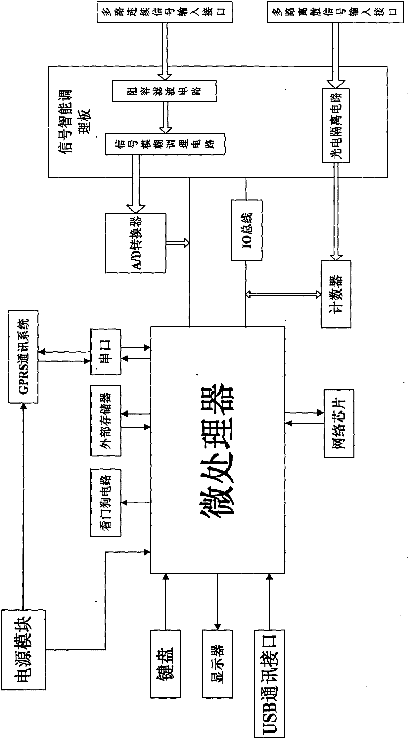
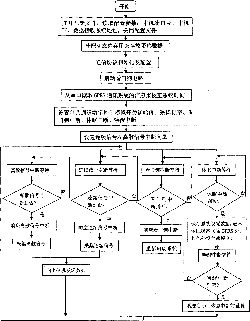
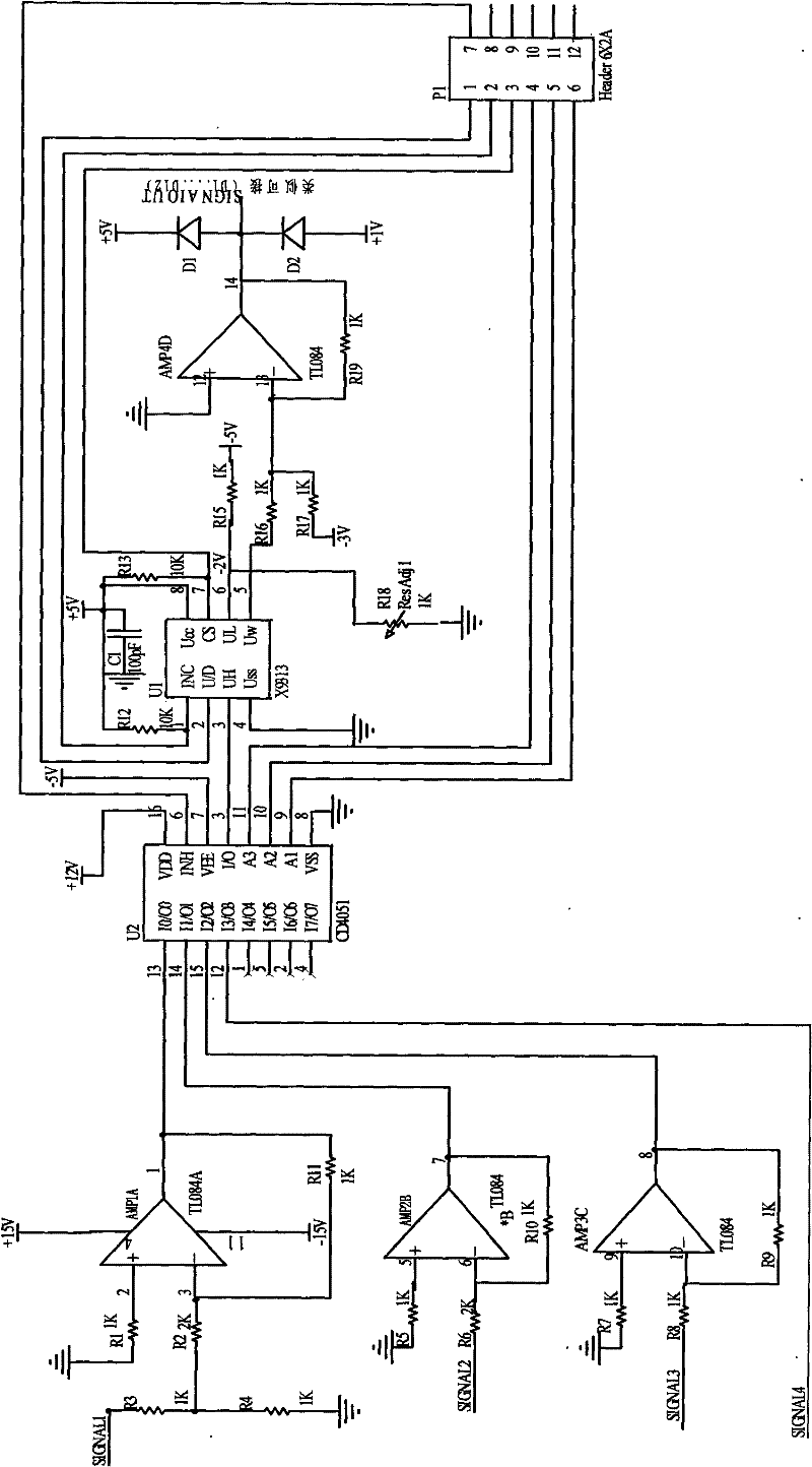

Image

  • Universal data acquisition unit
  • Universal data acquisition unit
  • Universal data acquisition unit

Examples


Embodiment Construction

[0043] The present invention will be further described below in conjunction with accompanying drawing and specific embodiment:

[0044] Such as figure 1 As shown, a general-purpose data acquisition device includes a microprocessor, a power supply module, a counter, an A / D converter and a signal intelligent conditioning board, and the multi-channel discrete signal input interface passes through the photoelectric isolation circuit in the signal intelligent conditioning board and the counter. The input terminals are connected, and the multi-channel continuous signal input interface is connected with the input terminals of the A / D converter through the signal fuzzy conditioning circuit in the signal intelligent conditioning board; the microprocessor is respectively connected with the A / D converter through the data bus It is connected with the output end of the counter, and the power supply module is connected with the microprocessor to provide the working voltage for the microproc...


PUM


Abstract

The invention relates to a universal data acquisition unit and a data acquisition method thereof, belonging to the technical field of data acquisition; the universal data acquisition unit comprises a microprocessor; a multi-path discrete signal input interface is connected with the input end of a counter by a photoelectric isolating circuit, and a multi-path continuous signal input interface is connected with the input end of an A / D converter, and a microprocessor is connected with the input ends of the A / D converter and the counter. The data acquisition method comprises that: system initialization is carried out; continuous and discrete signal interrupt vector is set; interrupt latency is carried out, if the discrete signal is interrupted, the discrete signal is acquired; if the continuous signal is interrupted, the continuous signal is acquired; if a watchdog is interrupted, a system is restarted; if hibernation is interrupted, system setting data is stored, and then a hibernation state is carried out; and then, interrupt latency awaken operation is carried out, if awakening is interrupted, the system is started, and the setting is restored before interruption; if the continuoussignal and the discrete signal are acquired, interrupt latency is continuously carried out after data is transmitted to an upper computer; if not, interrupt latency is carried out directly.

Description

Technical field: [0001] The invention belongs to the technical field of data acquisition, and in particular relates to a general data acquisition device and a data acquisition method thereof; it is used for monitoring dynamic parameters of telecommunication equipment rooms, base stations, power substations and power plants, detecting meteorological environment parameters, and complicated working conditions in the production process , Detection of various state signals in unattended industrial sites, monitoring of the operating status of fluid pipelines, environmental monitoring, etc. Background technique: [0002] Due to the diversity of on-site application conditions, the requirements for data acquisition devices are also diverse. Existing data acquisition devices generally have the problems of single function, low level of intelligence, low energy saving, and poor reliability. For example: the Chinese patent "universal data collector" with application number 200620017378....

Claims


Application Information

Patent Timeline
Patent Type & Authority Patents(China)
IPC IPC(8): G05B19/048
Inventor 冯健刘金海张化光杨宏宇历秀明
Owner NORTHEASTERN UNIV LIAONING
Learn More