Dust removing apparatus

A technology of dust removal device and dust removal head, which is applied in the direction of dust removal, electrical components, semiconductor/solid-state device manufacturing, etc., and can solve the problem of reducing dust removal capacity and other issues

Inactive Publication Date: 2010-03-10
HUGLE ELECTRONICS
View PDF8 Cites 18 Cited by
  • Summary
  • Abstract
  • Description
  • Claims
  • Application Information

AI Technical Summary

Problems solved by technology

When the switching valve is switched, fine foreign matter detached from the gasket for sealing may be mixed into the cleaning gas, which may reduce the dust removal ability

Method used


Image

  • Dust removing apparatus
  • Dust removing apparatus
  • Dust removing apparatus

Examples


Embodiment Construction

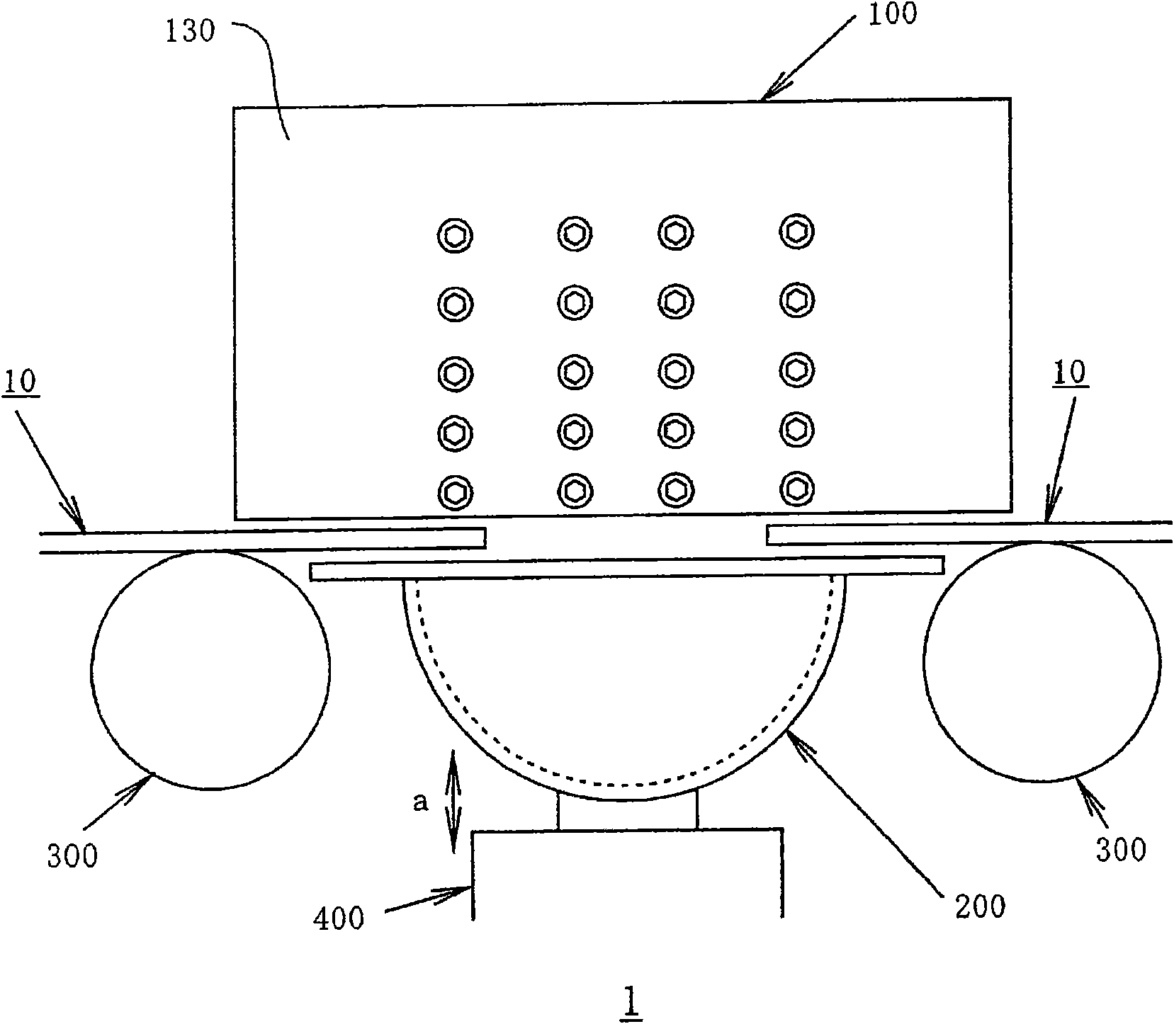
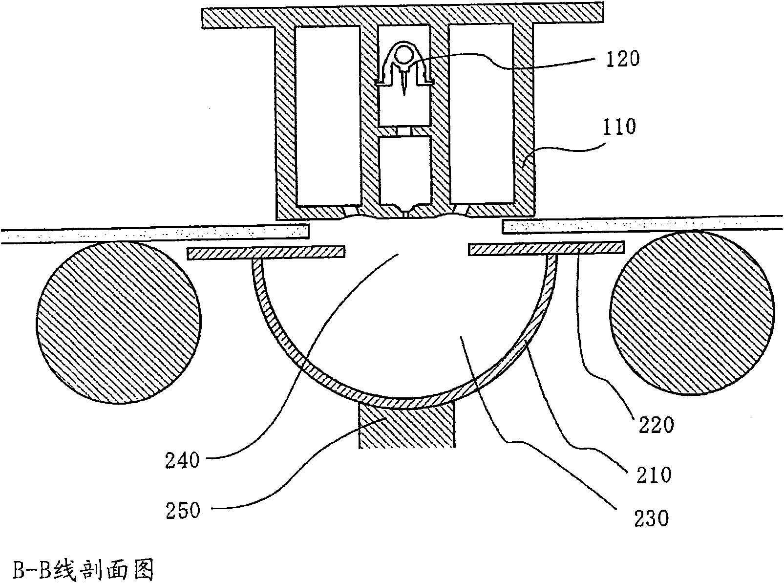
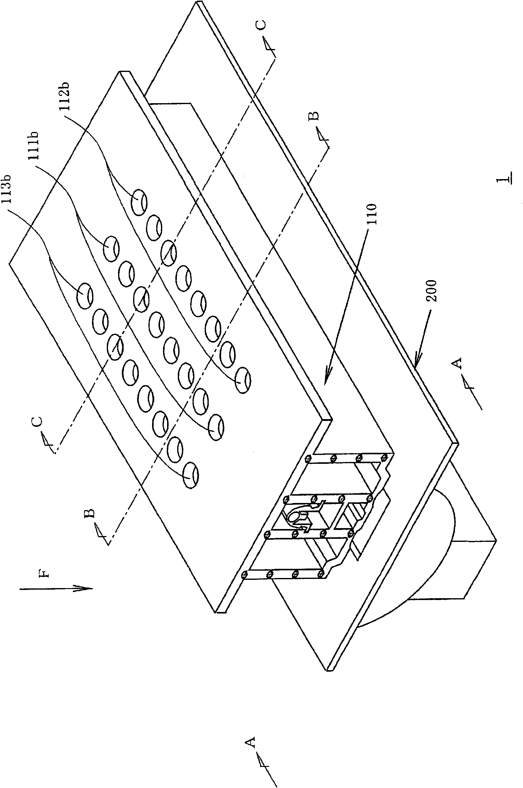
[0047] Next, the best mode for carrying out the present invention will be described with reference to the drawings. figure 1 It is a side view of the dust removal device of this form, figure 2 It is a sectional view of the dust removal device of this form, image 3 It is a three-dimensional external view of the dust removal device of this form. in addition, image 3 In the figure, the side wall is removed. The dust removal device 1 has a dust removal head 100 , a receiving unit 200 , a conveyance unit 300 , and a moving unit 400 . The dust removal device 1 removes dust from a dust removal target 10 .

[0048] In detail, the dust removal head 100 is figure 2 , image 3 The inside configuration ion generator 120 of shown dedusting head main body 110, further, on the both sides of dedusting head main body 110, be fixed as figure 1 The structure of the side wall portion 130 shown in .

[0049] The dust removal head 100 will be further described with reference to the dr...


PUM


Abstract

To provide a dust removing apparatus for removing dust from only one side of a dust removing object, in which a receiving unit having a simple configuration opposed to a dust removing head is added, after a flowing direction of cleaning gas from an injection chamber that passes through a gap between adjacent dust removing objects is changed, dust is sucked by a suction chamber, thereby reducing unnecessary scattering of dust. The dust removing apparatus 1 includes a receiving unit 200 that is located such as to be opposed to a dust removing head 100 and that changes a direction upon receptionof cleaning gas injected from an injection opening 111a of an injection chamber 111, the cleaning gas is injected from the injection opening 111a of the injection chamber 111 toward a gap between adjacent two dust removing objects 10, and the cleaning gas whose direction is changed by a receiving unit 200 is sucked from a suction opening 112a of the upper suction chamber 112 and a suction opening113a of a downstream suction chamber 113.

Description

technical field [0001] The invention relates to a dust removal device, which sprays a single cleaning gas such as air or rare gas to the dust removal object, including ultrasonic gas vibrating at ultrasonic frequency, gas containing positive and negative ions, or gas containing ultrasonic waves and ions at the same time ( Hereinafter they are collectively referred to as cleaning gas) for dust removal. Background technique [0002] For glass substrates such as TFT (Thin Film Transistor) liquid crystal panels, PDP (Plasma Display Panels), LCD (Liquid Crystal Displays), solar cell panels, or strips of paper, thin films, etc. object), and dust removal is carried out by the dust removal device. [0003] As a prior art example related to such a dust remover, the invention described in patent document (JP Unexamined-Japanese-Patent No. 2004-41851, title of invention "dust removal head") is known, for example. [0004] The prior art described in Patent Document 1 relates to a dust...

Claims


Application Information

Patent Timeline
Patent Type & Authority Applications(China)
IPC IPC(8): B08B5/00B08B15/04B08B7/00
CPCH01L21/67028
Inventor 管野盛利
Owner HUGLE ELECTRONICS
Why Eureka
Try Eureka