
Processing device used for vacuum coating

A processing device and vacuum coating technology, which are applied in vacuum evaporation coating, sputtering coating, ion implantation coating and other directions, can solve the problem of impure components of the coating layer of the substrate, affecting the stability of the performance of the substrate, and affecting the substrate performance. Quality life and other issues, to achieve the effect of improving quality and normal life, reducing impact, and connecting firmly and reliably

Inactive Publication Date: 2012-05-23
DONGGUAN ANWELL DIGITAL MASCH CO LTD
View PDF3 Cites 0 Cited by
  • Summary
  • Abstract
  • Description
  • Claims
  • Application Information

AI Technical Summary

Problems solved by technology

When in use, during the heating process before the OLED substrate is coated, there will be an evaporation source to evaporate the impurities before the evaporation temperature of the evaporator is reached, so that the evaporated impurities are first deposited on the surface of the substrate, causing the substrate The composition of the coating layer is impure, which affects the stability of the substrate performance and the firmness of the connection between the coating layer and the surface of the substrate
At the same time, because some evaporators will release gas during the heating and evaporation process, the pressure in the sealed cavity will rise, and the sealed cavity of the processing device will be subjected to different pressures, resulting in extremely uneven coating layers on the substrate, which will eventually affect the substrate. quality and normal lifespan

Method used


Image

  • Processing device used for vacuum coating
  • Processing device used for vacuum coating
  • Processing device used for vacuum coating

Examples


Embodiment Construction

[0022] In order to describe in detail the technical content and structural features of the processing device for vacuum coating of the present invention, further description will be made below in conjunction with the embodiments and accompanying drawings.

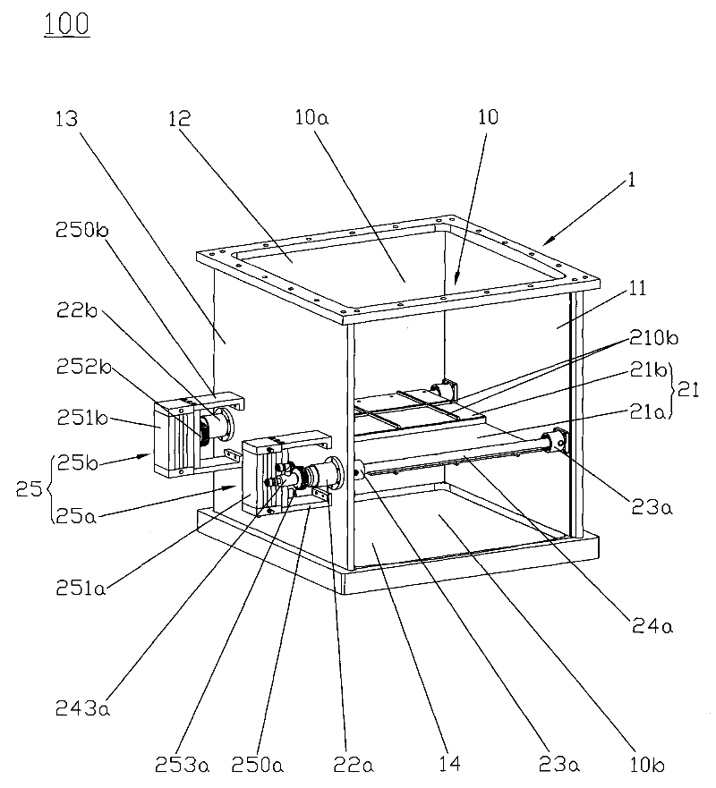
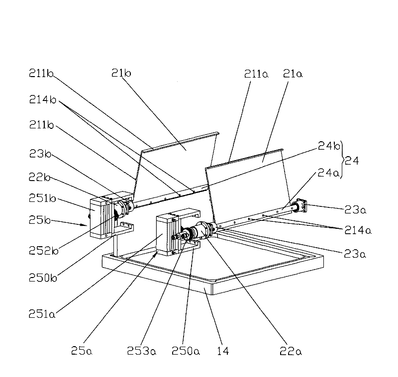
[0023] First, see figure 1 and figure 2 . exist figure 1 and figure 2Among them, the processing device 100 for vacuum coating of the present invention is used in the vacuum coating process of organic light emitting diodes, which includes a cabinet 1, a processing board and an evaporation source (not shown in the figure). This cabinet body 1 is formed by the sealing connection of left side plate 13, right side plate 11, front door plate (not shown in the figure), rear plate 12, bottom plate 14 and top plate (not shown in the figure), and above-mentioned left side plate 13. The right side panel 11 , the front door panel, the rear panel 12 , the bottom panel 14 and the top panel form the sealed chamber 10 of the cabinet ...


PUM


Abstract

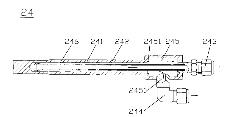
The invention provides a processing device used for vacuum coating. The device comprises a cabinet body, a processing board and an evaporation source, wherein the cabinet body takes a hollow structure that forms a sealing cavity; and the evaporation source and the processing board are arranged in the sealing cavity and the processing board is arranged above the evaporation source. Besides, the device also comprises a baffle mechanism and the baffle mechanism comprises a baffle, magnetofluid, a cooling shaft and a baffle driving mechanism, wherein the magnetofluid is arranged on the cabinet body; the baffle driving mechanism is arranged outside the cabinet body and connected with one end of the cooling shaft; the other end of the cooling shaft passes through the magnetofluid by pivotal connection and extends into the sealing cavity; the baffle is fixedly connected with the cooling shaft and arranged in the sealing cavity and between the evaporation source and the processing board, and isolates or opens the spatial join of the evaporation source and the processing board; and the baffle driving mechanism drives the cooling shaft and the cooling shaft drives the baffle to rotate. On the one hand, the processing device can improve the quality of a substrate coated layer to a maximum degree, and on the other hand, the normal service life of the processing device can be prolonged to a maximum degree.

Description

technical field [0001] The invention relates to a processing device for vacuum coating, in particular to a processing device for vacuum coating suitable for removing impurities in the vacuum coating process in organic light emitting diodes. Background technique [0002] OLED stands for Organic Light-Emitting Diode (Organic Light-Emitting Diode), also known as Organic Electroluminescence Display (OELD). Because of its thinness, power saving and other characteristics, it has been widely used on the display screen of digital products, and has great market potential. At present, the application of OLED in the world is focused on flat panel display, because OLED is the only one in the application A technology that can be compared with TFT-LCD, OLED is the only display technology that can produce large-size, high-brightness, and high-resolution soft screens among all current display technologies, and can be made into the same thickness as paper. Among them, in the OLED production...

Claims


Application Information

Patent Timeline
Patent Type & Authority Patents(China)
IPC IPC(8): C23C14/24C23C14/54
CPCC23C14/54C23C14/24
Inventor 杨明生范继良刘惠森王曼媛王勇
Owner DONGGUAN ANWELL DIGITAL MASCH CO LTD
Learn More