Micro-combustion equipment controlling air flow by using ionic wind

A micro-burner, ion wind technology, applied in the directions of gas fuel burners, burners, combustion methods, etc., can solve the problems of low energy consumption rate and low heat dissipation, achieve less heat dissipation, reduce wall heat loss, combustion good stability

Inactive Publication Date: 2010-03-10
SOUTH CHINA UNIV OF TECH
View PDF1 Cites 9 Cited by
  • Summary
  • Abstract
  • Description
  • Claims
  • Application Information

AI Technical Summary

Problems solved by technology

[0004] The purpose of the present invention is to overcome the shortcoming of prior art, provide a kind of micro-burner that utilizes ion wind to organize air flow, the present invention utilizes the ion wind formed by external stre

Method used


Image

  • Micro-combustion equipment controlling air flow by using ionic wind
  • Micro-combustion equipment controlling air flow by using ionic wind
  • Micro-combustion equipment controlling air flow by using ionic wind

Examples


Embodiment Construction

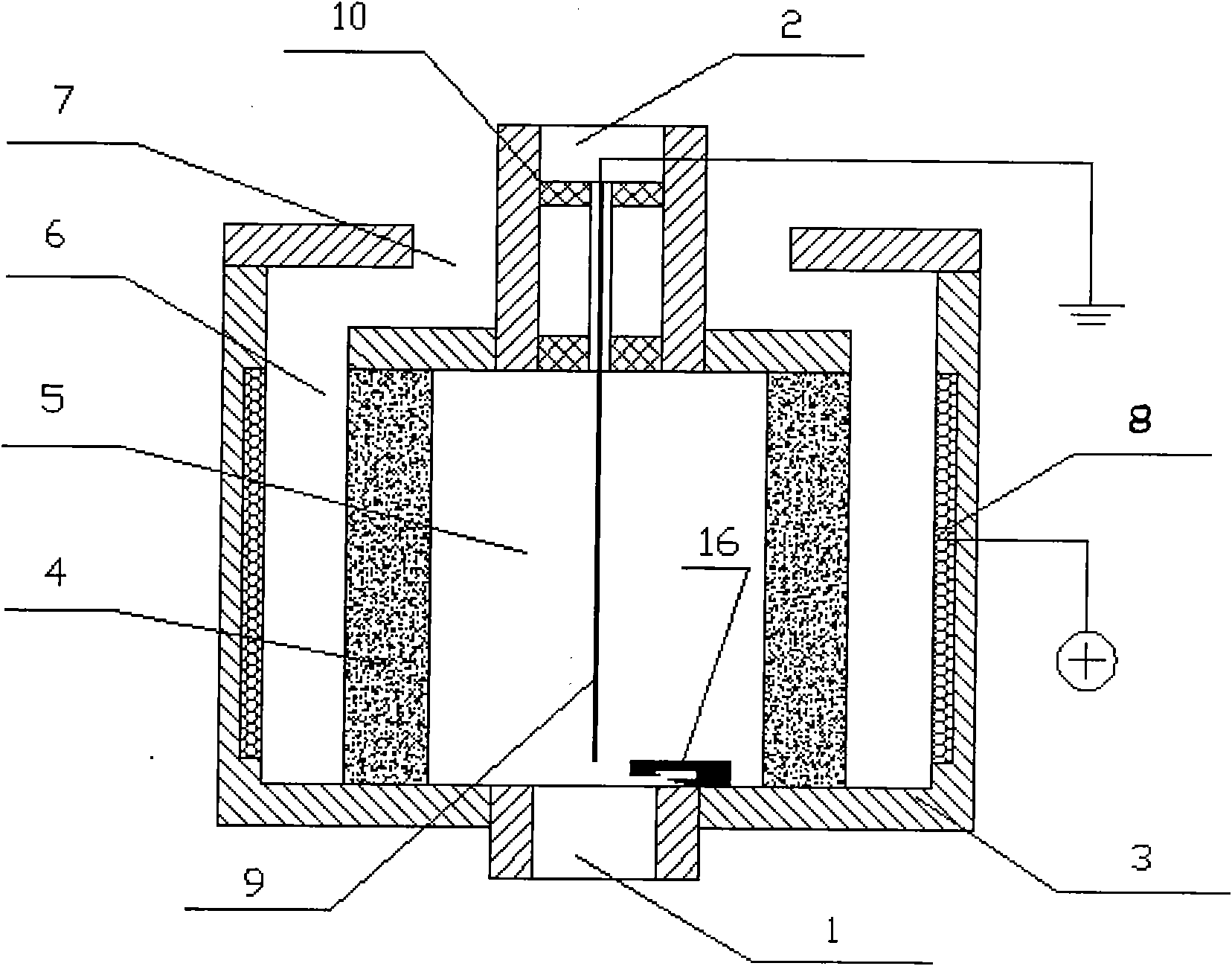
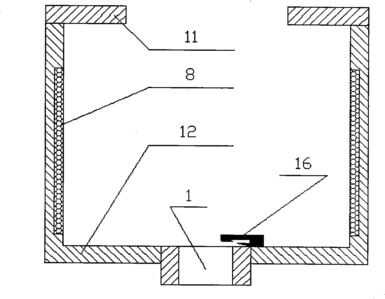
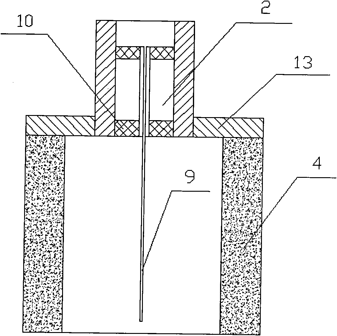
[0033] Such as figure 1 Shown, the micro-combustor of the present invention comprises outer casing wall 3, inner casing wall 4, fuel inlet hole 1, exhaust hole 2, air inlet hole 7 and electronic ignition device 16; Fuel inlet hole 1 and exhaust hole 2 are respectively located at both ends of the inner sleeve wall 4 in the axial direction. The side of the inner sleeve wall 4 is a porous material formed by sintering ceramic powder, with a thickness of 1mm and an air permeability of 30%. The outer sleeve wall 3 is made of ceramic material. The casing wall 4 forms an interlayer space 6, the sections of the fuel inlet hole 1, the exhaust hole 2, the inner casing wall 4 and the outer casing wall 3 are all circular, and the air intake hole 7 is formed between the outer casing wall 3 and the exhaust hole 2 In the annular gap, the micro burner is provided with an electrode device.

[0034] The electrode device consists of an electrode anode 8 and an electrode cathode 9, such as figu...


PUM

PropertyMeasurementUnit
Electric field strengthaaaaaaaaaa

Abstract

The invention discloses a micro-combustion equipment controlling air flow by using ionic wind, which comprises a fuel inlet (1), an air vent (2), an air inlet (7), an outer sheath wall (3), an inner sheath wall (4), an anode (8), a cathode (9) and an electronic lighter (16), wherein the cathode is a good needle-type high-temperature refractory conductor and the side surface of the inner sheath wall is made from a porous sintered material. A laminated space (6) is formed between the inner sheath wall and the outer sheath wall; the outer sheath wall and the air vent form the air inlet (7); the inner sheath wall is internally provided with a combustion chamber (5); and the anode is embedded or plated on the inner side of the outer sheath wall and the cathode is fixed on the central axial lineof the air vent by a cathode fixing plate (10). By the ionic wind produced by an external electric field, air is forced to flow so as to be in full contact with the fuel in the combustion chamber andensure full combustion; and simultaneously, the structure can effectively reduce heat loss and improve the combustion stability and combustion efficiency.

Description

technical field [0001] The invention relates to a micro-burner, in particular to a micro-burner which generates ion wind through an externally strengthened electric field, organizes air flow by using the ion wind, and promotes diffusion flame combustion. Background technique [0002] With the rapid development of micro-electro-mechanical systems (MEMS) technology, miniaturization has become a new trend in the trend of science and technology, such as various micro-aircraft and electronic equipment, and the successful development of tiny weapons in high-tech modern warfare has created a new era for people. At the same time, it also makes people realize the importance of micro energy systems. The obvious disadvantage of using lithium batteries for power supply of micro power devices is that its energy density is small, and the volume and weight of the energy supply system are relatively large. Therefore, it is of great importance to develop micro-energy systems that are small ...

Claims


Application Information

Patent Timeline
IPC IPC(8): F23D14/00F23D11/00
Inventor 甘云华矫明伦杨泽亮
Owner SOUTH CHINA UNIV OF TECH
Why Eureka
Try Eureka