Upper inlet wind type burner

A technology of burners and gas nozzles, which is applied in the directions of burners, gas fuel burners, combustion methods, etc., can solve the problems of large difference in heat load, inconsistent flame height, weak flame, etc., to prevent nozzle blockage and improve efficiency. , the effect of a short but powerful flame

Active Publication Date: 2010-03-10
GUANGDONG MACRO GAS APPLIANCE
View PDF5 Cites 16 Cited by
  • Summary
  • Abstract
  • Description
  • Claims
  • Application Information

AI Technical Summary

Problems solved by technology

[0002] Since domestic manufacturers introduced pure upward air intake burners from abroad in the late 1990s, they were quickly accepted by the market because of their simple and beautiful appearance. After domestic manufacturers have launched pure upward air intake burners with independent intellectual property rights , there are more upward air-intake burners on the market, but they all have defects such as poor combustion conditions, weak flames, and easy yellow flames.
Although some patents have made some improvements to address these defects, due to the poor heat dissipation performance of the upward air combustion system, the temperature of the burner will gradually increase with the prolongation of use time, resulting in a double increase in the viscosity of the gas near the burner. The thermal resistance increases, which in turn leads to a decrease in the thermal load, so the thermal load of the upward air intake burner in the cold state and the hot state differs greatly, and some even reach a 40% gap
This situation has brought great difficulties to the design of the upper air intake burner. If the air intake and intake air volume of the burner are designed according to the cold state, the air intake volume will be insufficient due to a sharp increase in air viscosity after working for a period of time. Yellow flame phenomenon occurs; if the air intake and intake air volume of the burner are designed according to the thermal state, the flame will be weak when the burner starts to work, and it is easy to cause the flame height to be inconsistent
At present, there is no effective way to solve this problem. We can only compromise a situation between the cold state and the hot state to design the upper air intake burner.

Method used


Image

  • Upper inlet wind type burner
  • Upper inlet wind type burner
  • Upper inlet wind type burner

Examples


Embodiment 1

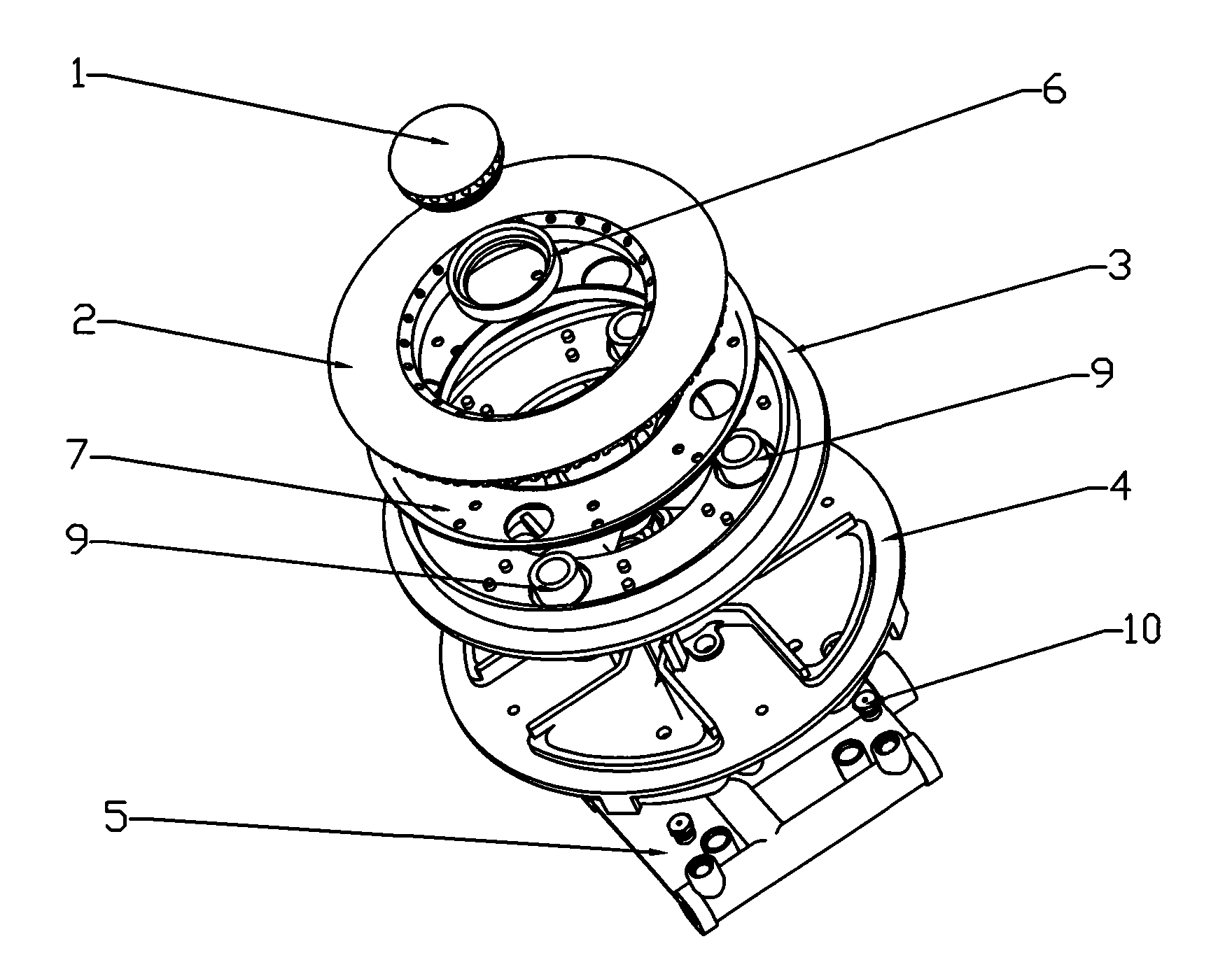
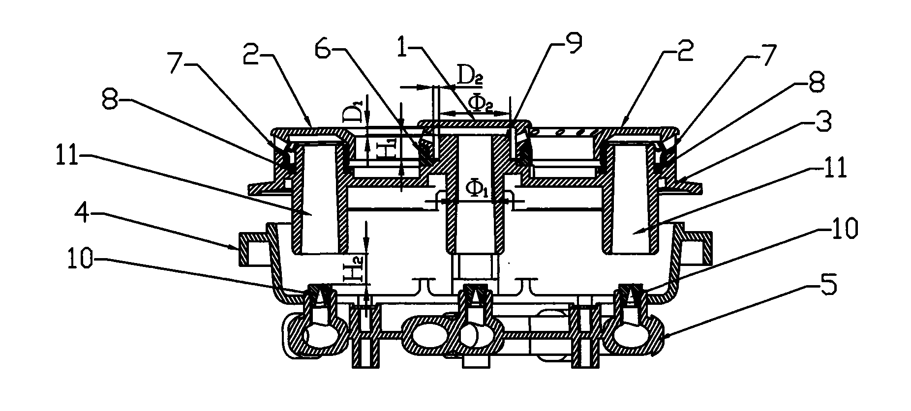
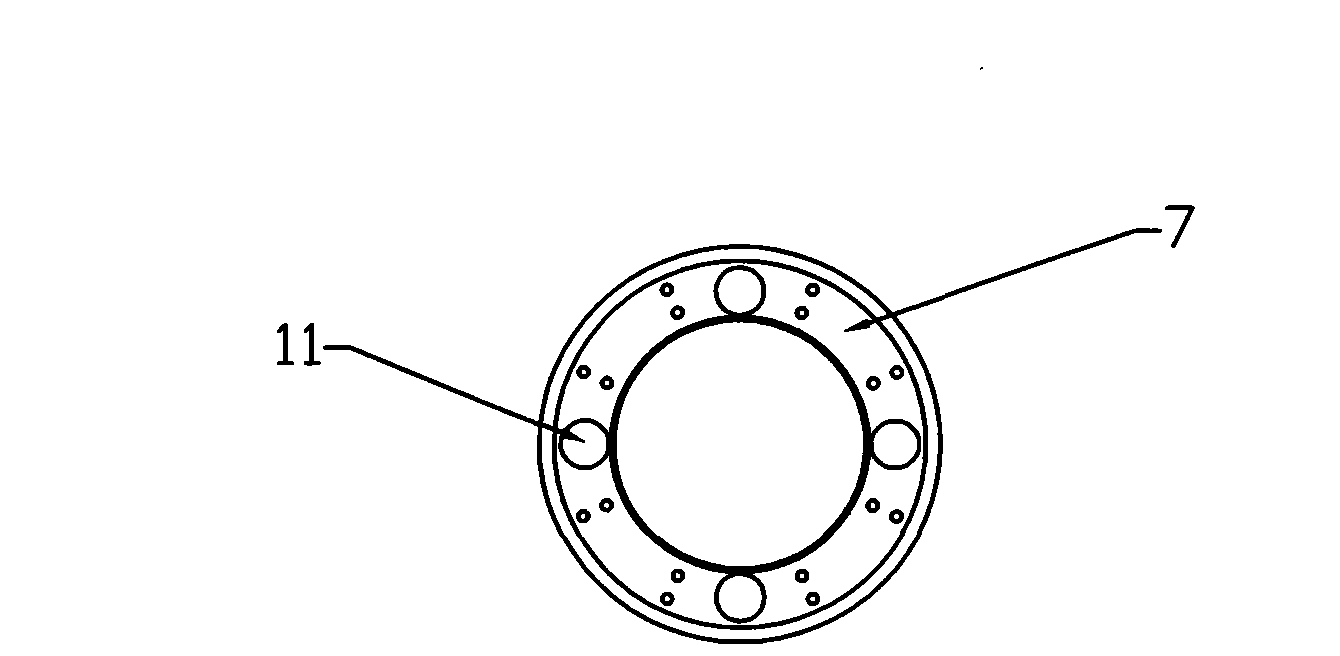
[0023] Such as Figure 1~5 As shown, the present invention discloses an upper air intake burner, which includes a central fire cover and an outer fire cover, a burner head, a base and a gas distribution pipe arranged sequentially from top to bottom, and the burner head is provided with five injection pipes, There is a gas mixing chamber on the base, five gas nozzles on the gas distribution pipe, and a gas distribution piece between the outer fire cover and the burner head. The gas distribution piece is in the shape of an annular groove. The positioning hole matched with the shooting tube, the upper end of the annular groove of the gas distributor is provided with an outward fold, the gas distributor is installed on the burner through the positioning hole, the outer fire cover is covered on the gas distributor; the center fire cover There is a fire cover seat between the furnace head and the fire cover seat. The fire cover seat is a cylindrical structure with a stepped inner ho...

Embodiment 2

[0025] In this embodiment, the values ​​of each parameter are limit values: H 1 = 2mm, D 2 =D 1 = 2.6mm, k 2 =3.9,k 1 =2.08, Φ 1 =10mm, Φ 2 =20.8mm, H 2=6mm, except that, all the other structures and functions are consistent with Embodiment 1. Although the value in this embodiment is the minimum limit value, the performance of the burner is still significantly improved compared with similar products, and it can still ensure that the injection tube has a strong injection force, the gas and air are fully mixed, and the flame is short and powerful. There are no defects such as yellow flame and tempering. If the value is further reduced, minor defects will develop into major defects.

Embodiment 3

[0027] In this embodiment, the values ​​of each parameter are the maximum limit value: H 1 =7mm,D 2 =D 1 = 2.4mm, k 2 =4.1,k 1 =2.29, Φ 1 =10mm, Φ 2 =22.9mm,H 2 =10mm, except that, all the other structures and functions are consistent with Embodiment 1. This embodiment can also ensure strong ejection force of the ejector tube, sufficient mixing of gas and air, short and powerful flame, and no defects such as yellow flame and tempering. If the value is further increased, defects will start to appear.

[0028] The above embodiments are burners designed using the functional relationship and value range provided by the present invention, and their working conditions and work efficiency can reach a relatively good state. The following table shows that the functional relationship and value range provided by the present invention are not adopted. Burners designed for the value range, they have more or less defects, as shown in the following table:

[0029] parameter...


PUM


Abstract

The invention discloses an upper inlet wind type burner comprising a central fire cover, an outer fire cover, a furnace end, a base and a gas distribution pipe which are sequentially arranged from top to bottom, wherein the furnace end is provided with a plurality of injection pipes, the base is provided with a gas mixing chamber and the gas distribution pipe is provided with a gas nozzle. A gas distribution slice is arranged between the outer fire cover and the furnace end, a fire cover seat is arranged between the central fire cover and the furnace end, and the fire cover seat is in a barrel structure with a ladder-shaped inner hole. By controlling the furnace temperature of the burner and improving the size, the invention greatly reduces the difference between cold working conditions and under hot working conditions of the upper inlet wind type burner, and thoroughly solves the problem of gas and air layering. The invention ensures that the flame is short and strong without yellow flame, backfire and other defects, has small size, large heat load and excellent burning condition and prevents the nozzle from being blocked.

Description

technical field [0001] The invention relates to the technical field of gas stoves, and more specifically relates to an upward air intake burner. Background technique [0002] Since domestic manufacturers introduced pure upward air intake burners from abroad in the late 1990s, they were quickly accepted by the market because of their simple and beautiful appearance. After domestic manufacturers have launched pure upward air intake burners with independent intellectual property rights , There are more upward air-intake burners on the market, but they all have defects such as poor combustion conditions, weak flames, and easy yellow flames. Although some patents have made some improvements to address these defects, due to the poor heat dissipation performance of the upward air combustion system, the temperature of the burner will gradually increase with the prolongation of use time, resulting in a double increase in the viscosity of the gas near the burner. The thermal resistan...

Claims


Application Information

Patent Timeline
Patent Type & Authority Applications(China)
IPC IPC(8): F23D14/04F23D14/46F23D14/64
Inventor 余少言仇明贵卢华师王克军
Owner GUANGDONG MACRO GAS APPLIANCE
Why Eureka
Try Eureka