Thermocouple slip ring device

A slip ring device and thermocouple technology, applied in the field of rotary kiln, can solve the problems of difficulty, high manufacturing cost and high cost of rotary kiln

Active Publication Date: 2010-03-10
ZHONGYE-CHANGTIAN INT ENG CO LTD
View PDF0 Cites 4 Cited by
  • Summary
  • Abstract
  • Description
  • Claims
  • Application Information

AI Technical Summary

Problems solved by technology

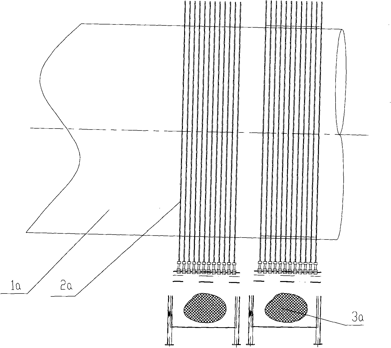
Moreover, the entire rotary kiln shell 1a needs to meet the installation requirements of 40 slip rings 2a, which is very difficult
In addition, the slip ring 2a is made of copper material, and the manufacturing cost is very high, which makes the cost of the entire rotary kiln very high

Method used


Image

  • Thermocouple slip ring device
  • Thermocouple slip ring device
  • Thermocouple slip ring device

Examples


Embodiment Construction

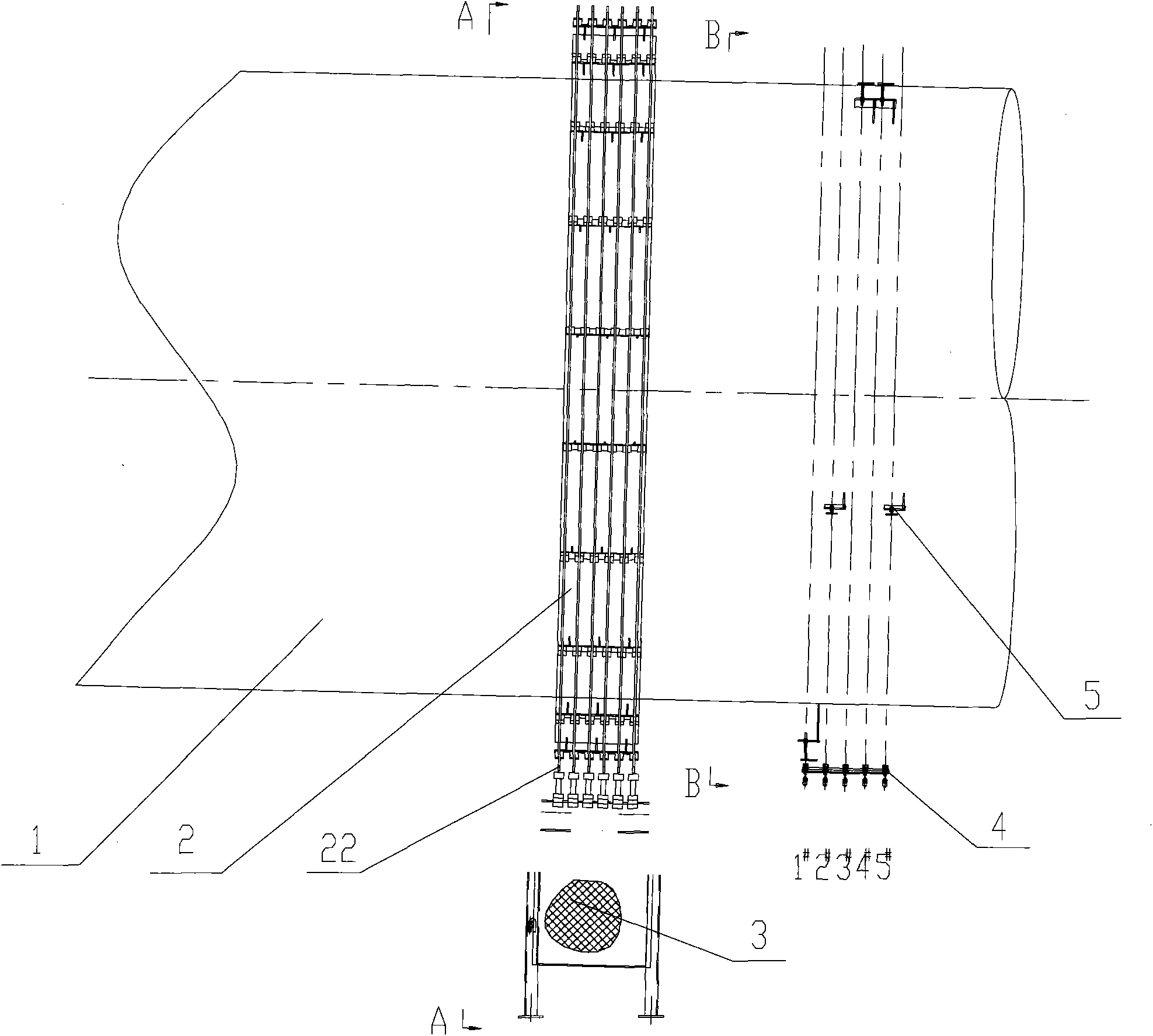
[0031] The invention provides a thermocouple slip ring device, which can not only meet the use requirement of obtaining thermocouple temperature signals, but also reduce the number of slip ring main bodies.

[0032] In order to facilitate the understanding of those skilled in the art, the structure and working principle of the thermocouple slip ring device described in the embodiment will be described in detail below with reference to the accompanying drawings.

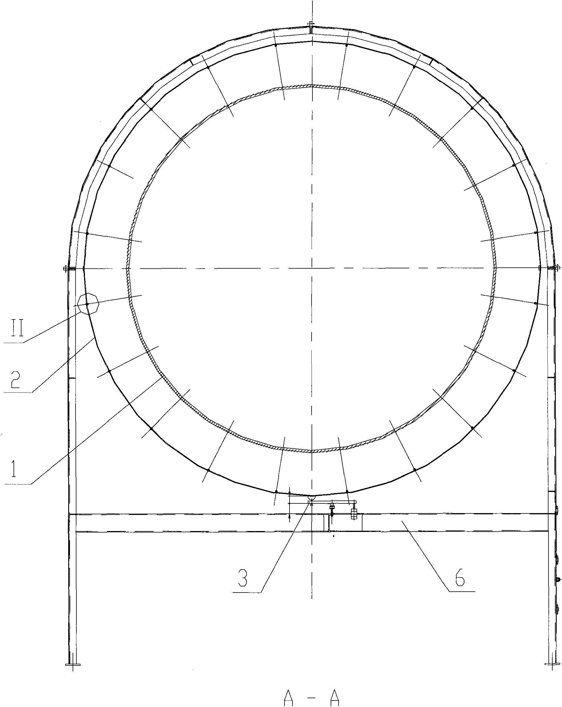
[0033] see Figure 1 to Figure 4 , figure 1 It is a structural schematic diagram of an existing thermocouple slip ring device; figure 2 It is the front view of the thermocouple slip ring device described in the embodiment of the present invention; image 3 Yes figure 2 A-A sectional view shown; Figure 4 Yes image 3 The enlarged view of part II shown; Figure 5 Yes figure 2 Shown is the B-B sectional view.

[0034] The thermocouple slip ring device in the embodiment of the present invention includes at lea...


PUM


Abstract

A thermocouple slip ring device comprises at least a group of slip rings. Each group of slip rings comprises two slip ring bodies which are respectively connected with the anode and the cathode. At least two insulators are synchronously arranged on the slip ring bodies of each group of slip rings. Slip ring sections between the insulators on the slip ring bodies are respectively connected with corresponding thermocouples by leads. The quantity of the slip ring sections is the same as that of the thermocouples. The thermocouple slip ring device also comprises an induction trigger device used for triggering the thermocouple slip rings and an electric brush used for collecting the thermocouple signals. The induction trigger device comprises induction contacts fixedly arranged on a cylinder body and inductors corresponding to the induction contacts. The quantity of the induction contacts is the same as the quantity of the slip ring sections on each group of slip ring bodies and the quantity of the inductors. When a certain induction contact is contacted with a corresponding inductor, the thermocouple temperature signals corresponding to the slip ring sections of all the groups of sliprings are collected and the slip ring sections correspond to the positions of the induction contacts. The thermocouple slip ring device of the invention can meet the use requirement of collecting thethermocouple temperature signals and reduce the quantity of the slip ring bodies.

Description

technical field [0001] The invention relates to a rotary kiln, in particular to a thermocouple slip ring device. Background technique [0002] In the direct reduction rotary kiln, it is necessary to measure the temperature at multiple positions in the rotary kiln shell (also called the rotary kiln rotor). Temperature measurement is generally achieved through thermocouples, which need two slip rings for positive and negative poles to supply power to realize the temperature signal acquisition of thermocouples. [0003] see figure 1 , which is a structural schematic diagram of an existing thermocouple slip ring device. The cylinder 1a of the existing rotary kiln needs temperature values ​​at about 20 different positions, so 20 thermocouples (not shown in the figure) need to be arranged at these 20 positions to measure the temperature at the corresponding positions. [0004] Since each thermocouple needs two slip rings 2a (one positive slip ring and one negative slip ring) to...

Claims


Application Information

Patent Timeline
Patent Type & Authority Applications(China)
IPC IPC(8): G01K7/02
Inventor 周慧玲戴传德陈猛胜秦愿
Owner ZHONGYE-CHANGTIAN INT ENG CO LTD
Why Eureka
Try Eureka