
Virtual multi-input multi-output relay transmission method based on space-time block coding

A technology of space-time block coding and transmission method, applied in the field of uplink relay transmission of LTE communication system, can solve the problems of low transmission capacity of user terminal and relay station link, inability to utilize diversity gain, additional occupation of time-frequency resources, etc.

Inactive Publication Date: 2010-03-10
CIVIL AVIATION UNIV OF CHINA
View PDF0 Cites 12 Cited by
  • Summary
  • Abstract
  • Description
  • Claims
  • Application Information

AI Technical Summary

Problems solved by technology

[0006] Compared with the non-relay uplink transmission scheme, the relay transmission scheme based on DFT-S-OFDM has the following advantages: it can improve the network coverage and overcome the blind spots of network communication, but in the relay communication system, this scheme has The link between the user terminal and the relay station occupies additional time-frequency resources, which brings the disadvantages of reduced system throughput and spectrum utilization
[0007] The single-antenna relay transmission scheme based on DFT-S-OFDM has the disadvantages of low transmission capacity of the link between the user terminal and the relay station, and low reliability of the link between the relay station and the base station. Disadvantages such as that the transmission reliability of user terminal links in edge cells or network blind areas cannot be fully guaranteed
And based on the DFT-S-OFDM single-antenna relay transmission scheme, when the number of relay stations is large, it has the disadvantage of increasing the detection complexity of the base station receiver

Method used


Image

  • Virtual multi-input multi-output relay transmission method based on space-time block coding
  • Virtual multi-input multi-output relay transmission method based on space-time block coding
  • Virtual multi-input multi-output relay transmission method based on space-time block coding

Examples


Embodiment Construction

[0063] The virtual MIMO relay transmission method based on block space-time block coding of the present invention will be described in detail below in conjunction with the accompanying drawings of the embodiments.

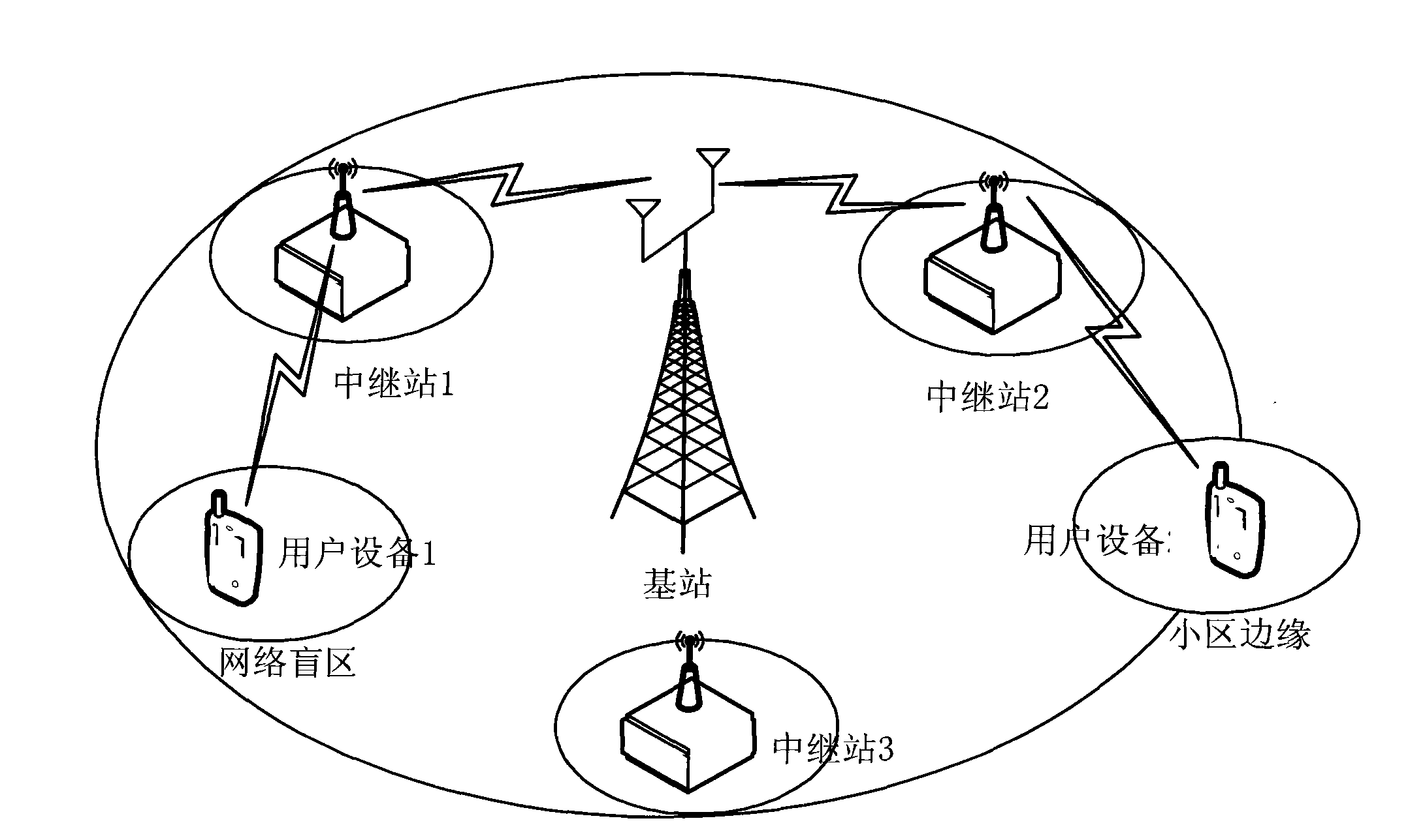
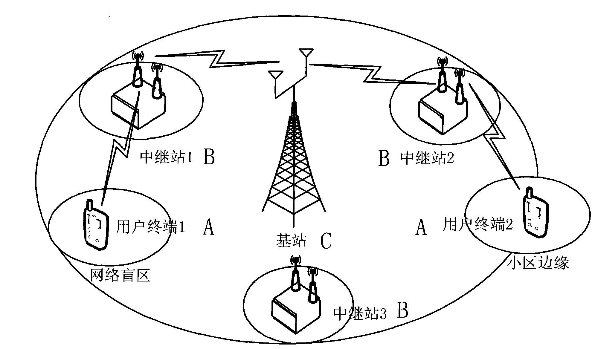
[0064] Such as figure 2 As shown, the base station (eNodeB) is located in the center of the cell, and several fixed relay stations (Relay) are deployed in the cell. There is no direct transmission link between the user terminal and the base station in the network dead zone and the cell edge, and the relay station is used for the cell edge and the network dead zone in a time-division manner. A terminal (UE) provides a relay transmission service. In the time division relay communication system, the time slot of the base station is divided into two parts, one part of the time slot is allocated to the link transmission between the user terminal and the relay station, and the other part of the time slot is allocated to the link between the relay station and the base st...


PUM


Abstract

The invention relates to a virtual multi-input multi-output relay transmission method based on space-time block coding. The chain between each relay station and each base station carries out transmission in a virtual MIMO manner of space-time block coding, and the chain between user equipment and a relay station carries out transmission in a maximum specific value combination manner. Each relay station transmitter in an uplink chain adopts the transmission manner of space-time block coding of two transmission antennas and uses the same time-frequency resource to communicate with a base station receiver under the base station dispatch. In the relay station receiver of the uplink chain, estimation and detection of the transmission modulating symbols on a user terminal are finished, and in the time slot of the subsequent relay station and the base station chain, the detected modulating symbols transmitted by the user terminal are transferred to the receiver of the base station. The base station receiver in the uplink chain finishes separation of user signals by adopting a multi-user space-time combined equalization algorithm. The invention increases the network coverage area, the uplink transmission volume and the frequency band use ratio and maintains low-peak average ratio of the transmitter in the uplink chain of the relay station.

Description

technical field [0001] The invention relates to an uplink relay transmission method of an LTE communication system. In particular, it relates to a block-space-time block coding-based virtual multiple-input multiple Output relay transport method. Background technique [0002] The uplink of the LTE system adopts the single carrier frequency division multiplexing (SC-FDMA) multiple access scheme, and the downlink adopts the orthogonal frequency division multiplexing (OFDMA) transmission scheme. At present, 3GPP has completed the standardization of the LTE Rel 8 system. However, there is a large gap between the LTE Rel8 system and ITU IMT-Advanced technical requirements, which is mainly reflected in the low user throughput and spectrum efficiency at the cell edge. In order to meet and exceed the requirements of the technical indicators of the IMT-Advanced system, 3GPP further launched the LTE-Advanced research plan. The goal of this plan is to optimize the uplink / downlink tran...

Claims


Application Information

Patent Timeline
IPC IPC(8): H04L1/06H04L1/00H04L25/03H04L27/26
Inventor 刘海涛王勇李冬霞
Owner CIVIL AVIATION UNIV OF CHINA
Learn More