Control device for vehicular power transmitting apparatus

A transmission device and vehicle power technology, which is applied in the direction of transmission device control, arrangement of multiple different prime movers of general power devices, power devices, etc., to achieve the effect of improving fuel economy performance

Active Publication Date: 2010-03-10
TOYOTA JIDOSHA KK
View PDF2 Cites 1 Cited by
  • Summary
  • Abstract
  • Description
  • Claims
  • Application Information

AI Technical Summary

Problems solved by technology

However, there is still room for the power transmission device forming part of the power transmission path extending from the internal combustion engine to the drive wheels to be optimized depending on the type of fuel

Method used


Image

  • Control device for vehicular power transmitting apparatus
  • Control device for vehicular power transmitting apparatus
  • Control device for vehicular power transmitting apparatus

Examples


Embodiment 1

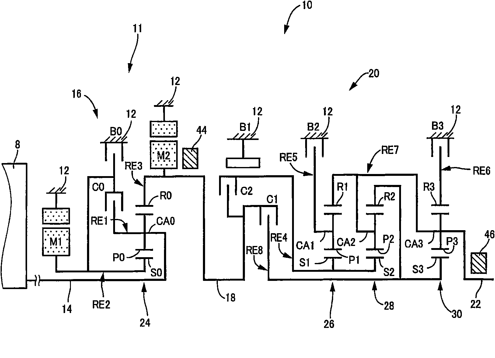
[0055] figure 1 is a block diagram showing a transmission mechanism 10 forming a part of a hybrid vehicle power transmission device to which a control device according to an embodiment of the present invention is applied. Such as figure 1 As shown in , the speed change mechanism 10 includes: an input shaft 14 serving as an input rotating member; Part 11. The transmission mechanism 10 also includes an automatic transmission portion 20 that passes through the differential mechanism 11 and drive wheels 38 via a power transmission member (power transmission shaft) 18 (see Figure 6 ) is connected in series to serve as a stepped transmission; and an output shaft 22 connected to the automatic transmission portion 20 as an output rotary member. All of these components are arranged in a transmission case 12 (hereinafter simply referred to as "case 12") for connecting non-rotating components mounted on the vehicle body.

[0056] The transmission mechanism 10 is preferably applicabl...

no. 1 example

[0152] Thus, the differential portion 11 (transmission mechanism 10) of this embodiment can be selectively switched to one of the continuously variable transmission state and the stepped transmission state (fixed transmission state). The switching control means 50 operates based on vehicle conditions to determine a shift state to which the differential portion 11 is to be shifted, thereby causing the shift state to be selectively switched to either one of a continuously variable state and a stepped state. With the first embodiment, the engine start-stop control means 66 starts or stops the engine 8 so that the hybrid control means 52 can operate to switch the engine drive mode and the motor drive mode based on the vehicle conditions.

[0153] Although the engine 8 is basically supplied with gasoline as fuel, there may be ethanol mixed with the gasoline fuel in certain proportions. In this case, the characteristics of the engine 8 are changed due to the mixing of ethanol. Ther...

no. 2 example

[0194] In the second embodiment, an electronic control unit 110 is used instead of Figure 4 The electronic control unit 40 of the first embodiment is shown in FIG. Figure 12 The functional block diagram of is showing the main control functions of the electronic control device 110 of the second embodiment. Figure 12 show with Figure 6 In the embodiment corresponding to the structure shown in , the differential mechanism switching condition changing device 88 of the first embodiment is replaced by the operating state switching condition changing device 112 . The second embodiment includes the same other means as the first embodiment, such as fuel supply determination means 80 , engine output torque detection means 82 , fuel change determination means 84 and fuel type determination means 86 . The second embodiment will be described below focusing on different points.

[0195] exist Figure 12 Among them, if the fuel change judging means 84 makes an affirmative judgment, i...


PUM


Abstract

A control device is disclosed which can obtain increased fuel economy performance depending on a kind of fuel in a vehicle having an internal combustion engine and an electric motor when the kind of fuel supplied to the internal combustion engine is altered. A determining vehicle speed (V 1 ) and determining output torque (T 1 ), representing a boundary value with which a step-variable control region and a continuously variable control region of a shifting mechanism ( 10 ) are demarcated, are altered such that the higher the mixing ratio of ethanol, the lower will be the determining vehicle speed (V 1 ) and determining output torque (T 1 ). Therefore, the determination is made whether to operate a first electric motor (M 1 ) depending on the mixing ratio of ethanol, making it possible to obtain increased fuel economy performance in line with the mixing ratio of ethanol.

Description

technical field [0001] The present invention relates to a control device for a vehicle power transmission device. More particularly, the present invention relates to a technique for obtaining improved fuel economy performance in a vehicle having an internal combustion engine and an electric motor when the kind of fuel supplied to the internal combustion engine is changed. Background technique [0002] One type of internal combustion engine includes a variable compression internal combustion engine in which the compression ratio can be changed. There has hitherto been known a control device capable of changing the compression ratio depending on the kind of fuel supplied to the variable compression internal combustion engine, such as hydrogen or gasoline. For example, Patent Publication 1 (Japanese Patent Application Laid-Open No. 2006-200508) discloses a control device for controlling an internal combustion engine. In addition, it is known that a technique has been disclose...

Claims


Application Information

Patent Timeline
Patent Type & Authority Applications(China)
IPC IPC(8): B60W20/00B60K6/445B60K6/547B60L50/16B60W10/06B60W10/08B60W10/10F16H59/74F16H61/00F16H61/68F16H61/684F16H61/688F16H63/50
CPCY02T10/6239Y02T10/6286B60W10/115B60W10/06B60K6/445Y02T10/36B60W2560/06F02D19/088B60W20/00F02D29/02Y02T10/56B60W2560/02F02D19/084B60W10/08B60W2530/209B60W2530/213Y02T10/30Y02T10/40Y02T10/62F02D19/08B60W10/10B60W10/04B60K6/44B60W20/15
Inventor 今村达也岩濑雄二田端淳
Owner TOYOTA JIDOSHA KK
Why Eureka
Try Eureka