
New method used for realizing powder melting and forming based on laser scanning

A laser scanning and new method technology, applied in the field of laser melting molding, can solve the problems of easy deformation of parts, cracks, and difficult thermal stress, etc., and achieve the effect of reducing distortion, improving molding efficiency, and not easy to warp deformation and cracks

Inactive Publication Date: 2010-03-17
HEILONGJIANG UNIVERSITY OF SCIENCE AND TECHNOLOGY
View PDF0 Cites 32 Cited by
  • Summary
  • Abstract
  • Description
  • Claims
  • Application Information

AI Technical Summary

Problems solved by technology

[0004] In order to solve the technical problems of low efficiency of single-beam laser melting molding in the world, easy deformation and cracks of parts after molding, and difficult control of thermal stress, this invention designs a new method based on laser scanning to realize powder melting molding. One kind of laser and two sets of vibrating mirror systems are used for compound scanning melting and forming, the laser scanning is uniform, and the deformation is not easy to occur

Method used


Image

  • New method used for realizing powder melting and forming based on laser scanning
  • New method used for realizing powder melting and forming based on laser scanning

Examples


Embodiment Construction

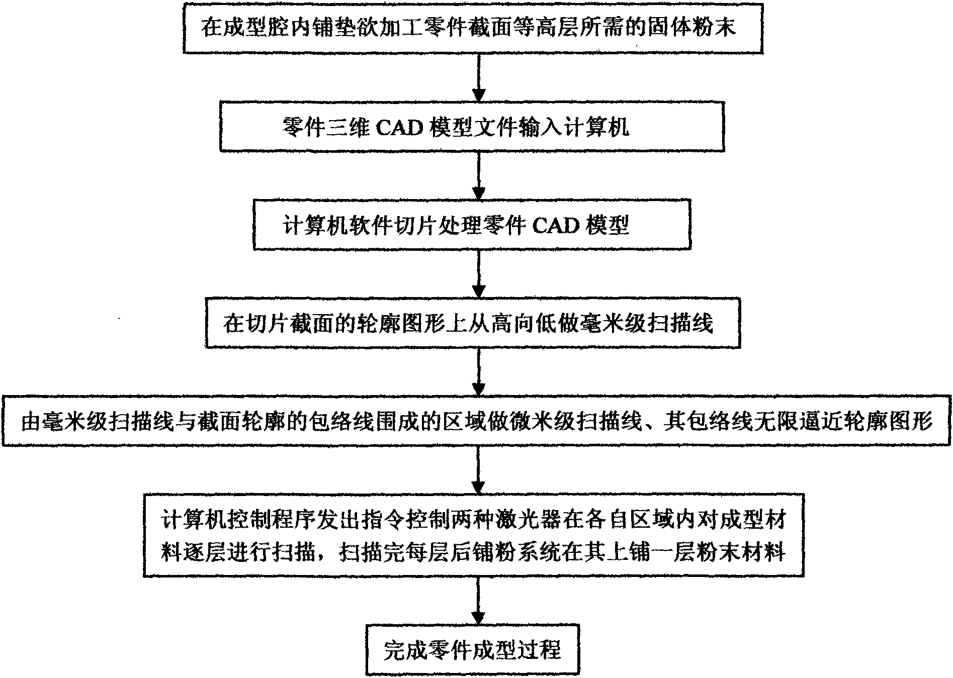
[0011] see figure 1 , a new method based on laser scanning to realize powder melting molding. This method scans and melts sintered materials by means of lasers, vibrating mirror systems and supporting computer control software programs. For solid powder, the cross-section information of the processed parts is extracted by software. With the help of computer control, the laser scans layer by layer according to the cross-section information of the part model. After each layer of solid powder is melted and formed under laser scanning, the next layer of solid powder is laid for the next layer Prepare for the first laser scan, and scan layer by layer until the entire molding process is completed. The above method uses two types of lasers and a matching galvanometer system to scan the area of ​​each layer of solid powder synchronously according to the contour graphics of the section section. Each area is scanned layer by layer to complete the powder fusion molding. The above-mention...


PUM

PropertyMeasurementUnit
lengthaaaaaaaaaa
widthaaaaaaaaaa
radiusaaaaaaaaaa

Abstract

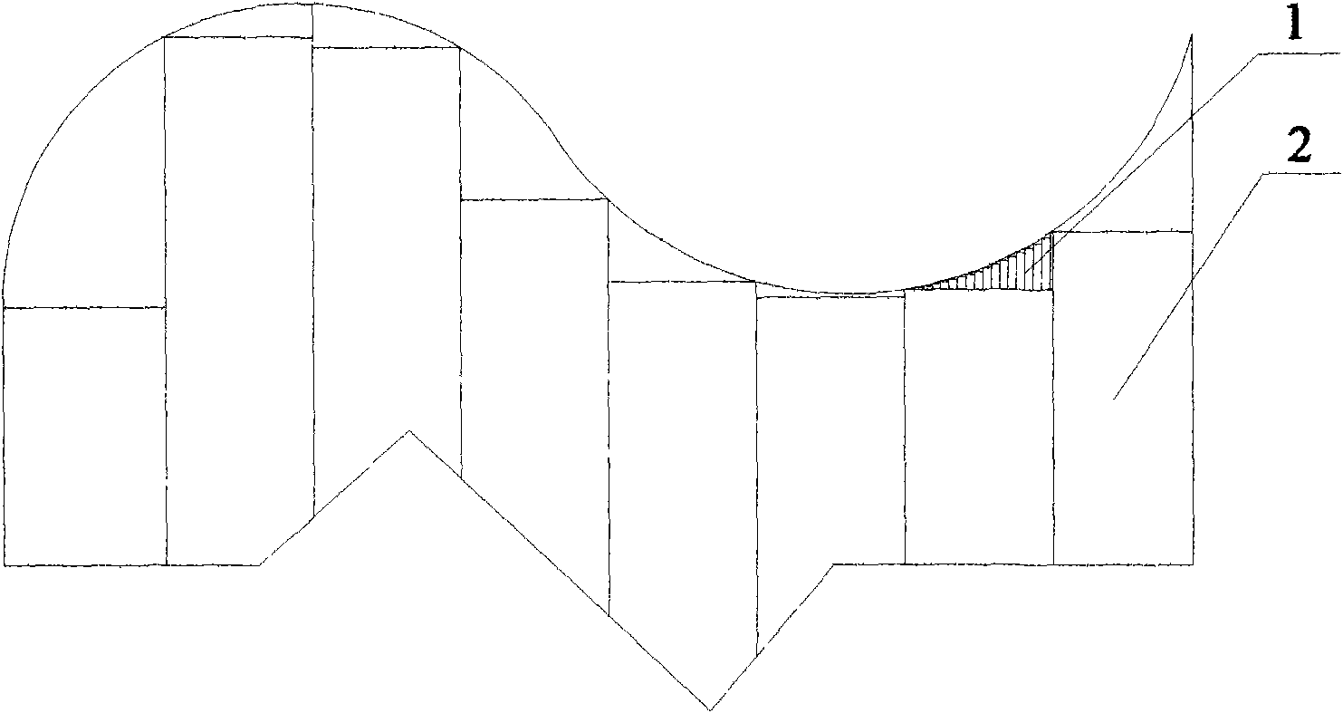
The invention relates to a new method used for realizing powder melting and forming based on laser scanning, aiming at solving the technical problems that the efficiency is low by adopting single beamof laser for melting and forming, parts are easy to be deformed and cracked after forming, and the thermal stress is difficult to be controlled. A technical scheme is adopted as follows: two types oflasers and matched vibration mirror systems are adopted; according to a contour pattern of a cross-section of a slice, each layer of solid powder is subjected to area scanning synchronously; and scanning is carried out layer by layer by the two types of lasers in each area so as to finish the powder melting and forming, wherein an area dividing method comprises the steps of respectively scanningand dividing parallelly a cross-section image by scanning lines in millimetre and micrometer so as to form a rectangular fast scanning area in millimetre and a curve edge fine scanning area in micrometer and lead the envelope curve pattern of the curve edge fine scanning area in micrometer to be approximate to the contour pattern infinitely. The method has the advantages that two lasers are adopted for compound scanning; the time is saved; the part forming efficiency is improved; and the part is not easy to be buckled and deformed and cracked.

Description

technical field [0001] The invention relates to the technical field of laser melting molding, and relates to a new method for realizing powder melting molding based on laser scanning, in particular to a method for scanning and molding in subregions by using two kinds of lasers. Background technique [0002] Laser rapid prototyping manufacturing technology is a high-tech laser prototyping developed in the 1980s. Among them, the selective laser forming technology uses solid powder as the sintering molding material. The CAD three-dimensional model of the part is input into the computer, and then the section information file is generated through slicing. The computer controls the laser forming layer by layer. Prototype or parts needed. This technology has the characteristics of wide range of molding materials, the manufacturing process is not affected by the complexity of parts, high manufacturing efficiency and low cost, and is especially suitable for manufacturing complex str...

Claims


Application Information

Patent Timeline
Patent Type & Authority Applications(China)
IPC IPC(8): B22F3/105
Inventor 刘锦辉赵灿陈继兵李瑞迪
Owner HEILONGJIANG UNIVERSITY OF SCIENCE AND TECHNOLOGY
Learn More