Frequency conversion generator set

A technology for generator sets and generators, applied in electric components, machines/engines, electrical components, etc., can solve the problems of unbalanced structure ratio of generator sets, narrowing of silicon steel sheet extremely wide bandwidth, and increased cost of engines, and the improvement process is simple and convenient. , increase the volume, improve the effect of cost saving

Inactive Publication Date: 2010-03-17
陈维加
View PDF0 Cites 8 Cited by
  • Summary
  • Abstract
  • Description
  • Claims
  • Application Information

AI Technical Summary

Problems solved by technology

[0007] 1. Use an engine with a higher speed to replace the current engine to increase the frequency of the generator. However, the increase in speed undoubtedly creates higher requirements for engine components, which makes the cost of the engine significantly higher; The loss is also large, the corresponding maintenance cost is also high, and there are also disadvantages of high noise and large vibration
[0008] 2. Increase the frequency of the generator by increasing the diameter of the stator of the multi-pole generator and increasing the magnetic poles. However, the result is that the volume of the generator is too large, which leads to an imbalance in the structure of the entire generator set
[0009] 3. Under the condition that the diameter of the multi-pole generator stator remains unchanged, the frequency of the generator is increased by increasing the number of magnetic pole pairs. However, the increase in the number of magnetic pole pairs reduces the slot area on the stator, making it impossible to wind and Coils that match the power, and also make the pole width of the silicon steel sheet that constitutes the magnetic pole narrow, and the strength is greatly reduced

Method used


Image

  • Frequency conversion generator set
  • Frequency conversion generator set
  • Frequency conversion generator set

Examples


Embodiment

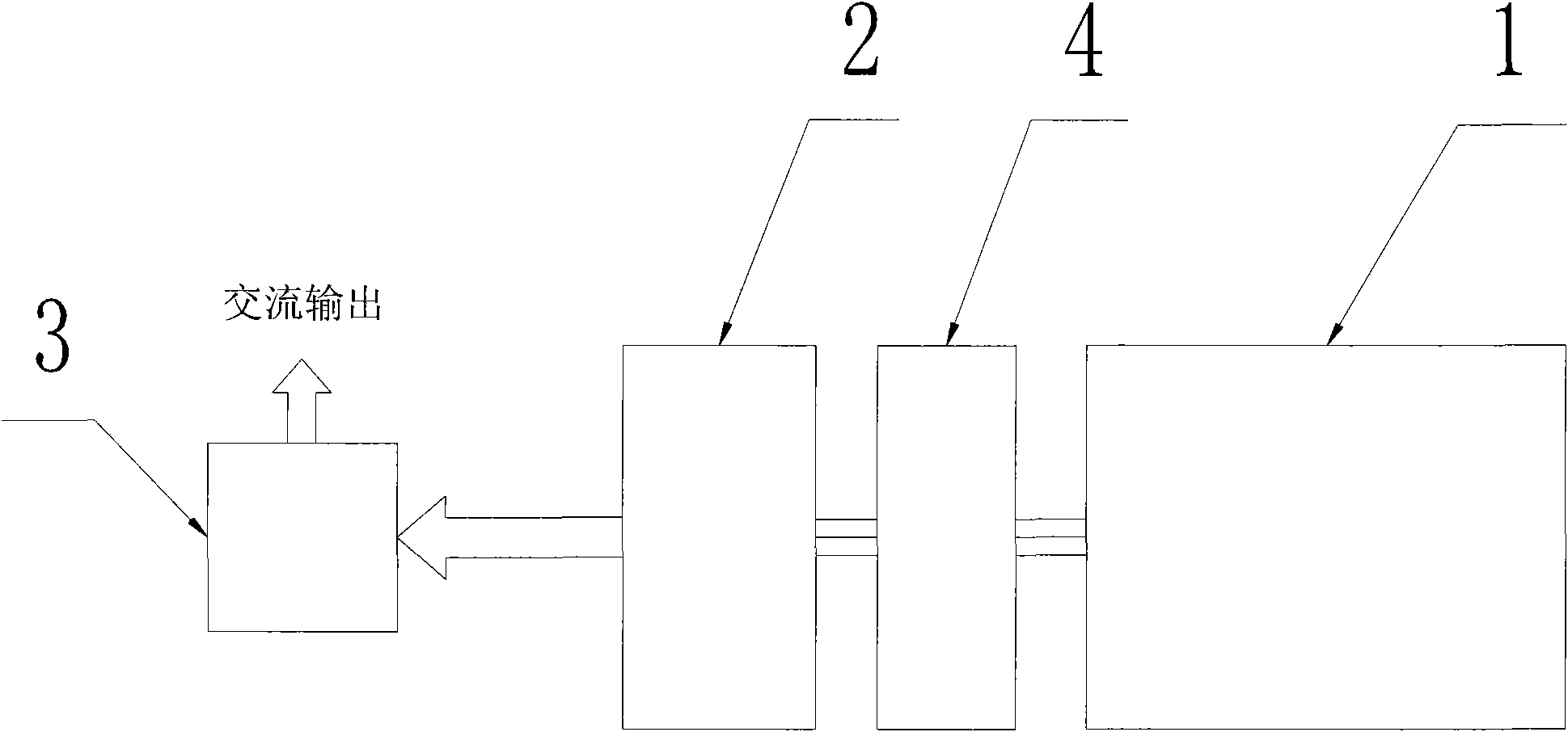
[0022] Example: figure 1 Shown is a specific embodiment of the frequency conversion generating set of the present invention, which includes a multi-pole generator 2, an engine 1 whose output end is connected to the input end of the multi-pole generator 2, and an engine 1 whose input end is connected to the output end of the multi-pole generator 2 AA type frequency conversion converter 3; a speed increaser 4 is installed between the output end of the engine 1 and the input end of the multi-pole generator 2.

[0023] When this embodiment is working, the engine 1 drives the multi-pole generator 2 to run by increasing the speed through the speed increaser 4, so that the frequency of the AC voltage output on the stator of the multi-pole generator 2 is further increased, and the AC voltage is further converted by AA type frequency conversion The thyristor rectifier circuit in the device 3 converts it into the required sinusoidal alternating current output, and its waveform distortio...


PUM


Abstract

The invention discloses a frequency conversion generator set. The frequency conversion generator set comprises a multipolar generator, an output terminal, an engine connected with an input terminal ofthe multipolar generator, the input terminal and an AA-type frequency converter connected with the output terminal of the multipolar generator; and the frequency conversion generator set is characterized in that a speed increaser is arranged between the output terminal of the engine and the input terminal of the multipolar generator. With the speed increaser arranged on the output terminal of theengine, the frequency conversion generator set increases speed of the engine, increases frequency of the generator so as to further reduce degree of wave distortion of voltage output by the AA-type frequency converter and allow the AA-type frequency converter to be effectively used in the frequency conversion generator set, thus improving efficiency of the generator and reducing weight and size of the generator set. Meanwhile, cost for improvement of the frequency conversion generator set is also reduced due to very simple and convenient improvement process.

Description

technical field [0001] The invention relates to a frequency conversion generating set. Background technique [0002] Existing frequency conversion generating sets usually use the engine to drive the multi-pole generator to generate high-frequency equal-amplitude alternating current, and then convert it into 50Hz or 60Hz sinusoidal alternating current through the rectification and inverter circuit in the ADA type variable frequency converter. The above is to chop the DC at a frequency of about 20K and then filter it with an inductor to restore the output waveform to a 50Hz or 60Hz sine wave AC. Because the frequency of 20K has a lot of energy, it is easy to generate high-order harmonics and radiate to the Electromagnetic interference is produced in the air; in addition, expensive high-power semiconductor power devices and large-capacity capacitors are generally used in ADA-style rectification and inverter circuits. power generator. [0003] On the contrary, the current AA p...

Claims


Application Information

Patent Timeline
Patent Type & Authority Applications(China)
IPC IPC(8): F02B63/04H02K7/18
Inventor 陈维加
Owner 陈维加
Why Eureka
Try Eureka