
Parallel stream heat exchanger integrated with microchannel and outer fin

A technology of parallel flow heat exchanger and microchannel, which is applied in the direction of heat exchange equipment, evaporator/condenser, lighting and heating equipment, etc., which can solve the complex processing of the shell connected to the heat sink, the increase of refrigerant flow resistance, The processing process is cumbersome and other problems, to achieve the effect of reducing material cost, increasing heat transfer, and eliminating contact thermal resistance

Inactive Publication Date: 2010-03-17
SOUTH CHINA UNIV OF TECH
View PDF1 Cites 14 Cited by
  • Summary
  • Abstract
  • Description
  • Claims
  • Application Information

AI Technical Summary

Problems solved by technology

However, the processing of the shell connecting the heat sink is complicated, the flow resistance of the refrigerant is increased, and the heat sink is fixed by screw connection, which is not only cumbersome in the processing process, not conducive to mass production, but also increases the cost, and the heat transfer performance is also reduced; It is far less convenient than the connection of parallel flow headers, and the cost is low

Method used


Image

  • Parallel stream heat exchanger integrated with microchannel and outer fin
  • Parallel stream heat exchanger integrated with microchannel and outer fin
  • Parallel stream heat exchanger integrated with microchannel and outer fin

Examples


Embodiment Construction

[0025] The present invention will be further described below in conjunction with the accompanying drawings and examples. It should be noted that the protection scope of the present invention is not limited to the scope described in the embodiments.

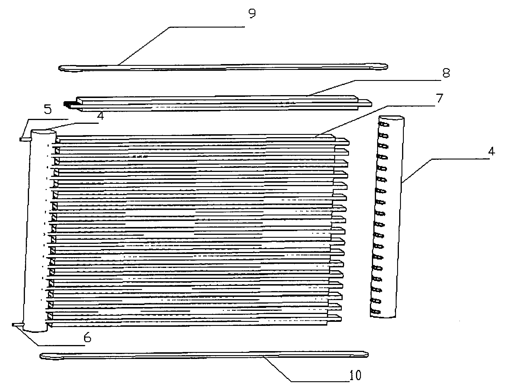
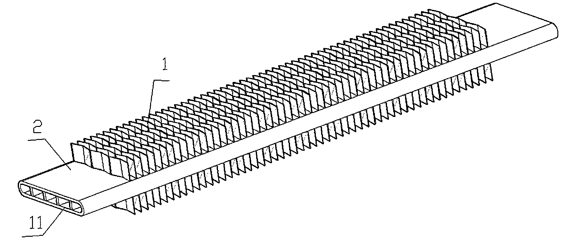
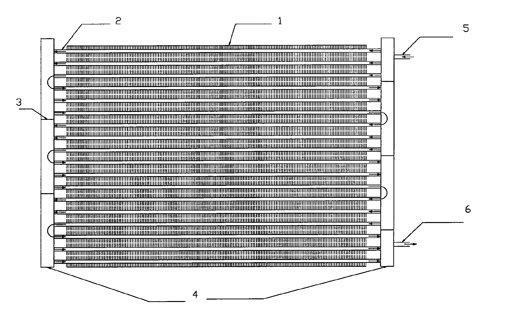
[0026] Such as Figure 1~3 As shown, a parallel flow heat exchanger in which microchannels and outer fins are integrally formed includes left and right liquid collecting pipes 4, an upper cover plate 9, a lower cover plate 10, a cooling fin group 7, an air inlet pipe 5 and a liquid outlet pipe 6; The heat sink group 7 is formed by connecting multiple heat sinks 8 side by side, and is located in the frame structure composed of the upper cover plate 9, the lower cover plate 10 and the left and right liquid collection pipes 4; the heat sink 8 is composed of fins 1 and aluminum profiles 2. Forming, there are micro-channels 11 on the aluminum profile, and the micro-channels 11 have several shapes of circle, rectangle and ellipse. The d...


PUM

PropertyMeasurementUnit
Heightaaaaaaaaaa
Thicknessaaaaaaaaaa

Abstract

The invention discloses a parallel stream heat exchanger integrated with a microchannel and an outer fin, comprising a left collector tube, a right collector tube, an upper cover board, a lower coverboard, a cooling fin set, an air inlet pipe and a liquid outlet pipe; the cooling fin is integrated with a fin and aluminium profile, a microchannel is arranged on the aluminium profile, and the diameter or edge distance of the microchannel is 0.5-3mm; the microchannel of the cooling fin is communicated with the left collector tube and the right collector tube, distance pieces which are arrayed ina staggering way are arranged in the middle of the left and right collector tubes at interval, the left and right collector tubes are divided into a plurality of areas, the air inlet pipe and the liquid outlet pipe and the left and right collector tubes are connected by welding, and the upper cover board and the lower cover board are respectively connected with the left and right collector tubes;by utilizing the microchannel technology, integral outer fin technology and collector tube technology, the invention effectively solves the problem of thermal contact resistance of sheets and the fins; the structure is compact, heat exchanging efficiency is high, the volume is small, the quality is light, the processing is simple, and the heat exchanger adopts all aluminium composite material, thereby greatly reducing the cost.

Description

technical field [0001] The invention relates to a heat exchanger, in particular to an energy-saving, environment-friendly, low-cost parallel flow heat exchanger in which microchannels and outer fins are integrally formed. technical background [0002] At present, an air conditioner is composed of a condenser, an evaporator, a compressor, and a throttling device. The heat exchanger including the evaporator and the condenser is an important component of the air conditioner, and its quality directly affects the performance of the air conditioner product. According to reports, the heat loss of the heat exchanger accounts for 2 / 3 of the heat loss of the entire air conditioner. From the perspective of air-conditioning products in the market, most air-conditioning heat exchangers are generally divided into three types according to the tube type and structure of the heat exchange tubes used, tube-belt type and parallel flow type. The heat-exchanged refrigerant is introduced into th...

Claims


Application Information

Patent Timeline
IPC IPC(8): F25B39/00F28F3/08F28F3/12
Inventor 汪双凤李炅潘娜赖昆盛
Owner SOUTH CHINA UNIV OF TECH
Learn More