
A refrigerator device

A technology for refrigerators and cooling capacity, which is applied in the direction of household refrigeration devices, refrigerators, coolers, etc., and can solve the problem of small contact area between the cold guide tube and the cold end adapter, no increase in the cooling capacity of the Stirling refrigerator, and the condensation of the working medium Insufficient problems, to achieve the effect of eliminating contact thermal resistance, increasing cooling capacity, and sufficient heat exchange

Active Publication Date: 2020-11-03
UNIV OF SHANGHAI FOR SCI & TECH
View PDF6 Cites 1 Cited by
  • Summary
  • Abstract
  • Description
  • Claims
  • Application Information

AI Technical Summary

Problems solved by technology

[0003] However, in the mobile cold chain box in the prior art, a cold end adapter is provided outside the cold end of the Stirling refrigerator, and the cold end adapter is combined with the cold guide tube to transfer the cold energy of the Stirling refrigerator to the inside of the box. , the disadvantage of such a device is that the contact area between the cold guide tube and the cold end adapter is too small, which will lead to insufficient condensation of the working medium in the cold guide tube and poor cooling performance; in addition, a single Stirling refrigerator is used as a cold The cold source of the chain box must be equipped with a shock absorber to absorb the vibration of the refrigerator during operation. Usually, the mass of the shock absorber is 0.1 to 0.3 times the mass of the Stirling refrigerator, so that the mass of the whole machine increases and increases The quality of the Stirling refrigerator does not increase the cooling capacity of the Stirling refrigerator, and the cooling capacity of the refrigerator of the same quality is reduced

Method used


Image

  • A refrigerator device
  • A refrigerator device
  • A refrigerator device

Examples


Embodiment Construction

[0023] In order to make the technical means, creative features, goals and effects of the present invention easy to understand, the following embodiments will specifically illustrate the refrigerator device of the present invention in conjunction with the accompanying drawings.

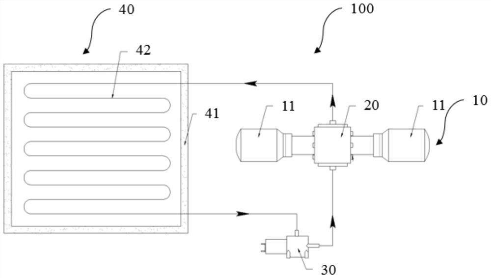
[0024] figure 1 It is a structural schematic diagram of the condensation box device in the embodiment of the present invention. Wherein, the direction of the arrow in the figure is the flow direction of the brine.

[0025] Such as figure 1 As shown, the refrigerator device 100 is used to refrigerate items, and includes a refrigeration unit 10 , a cooling guide unit 20 , a brine pump 30 and a refrigerator box body 40 .

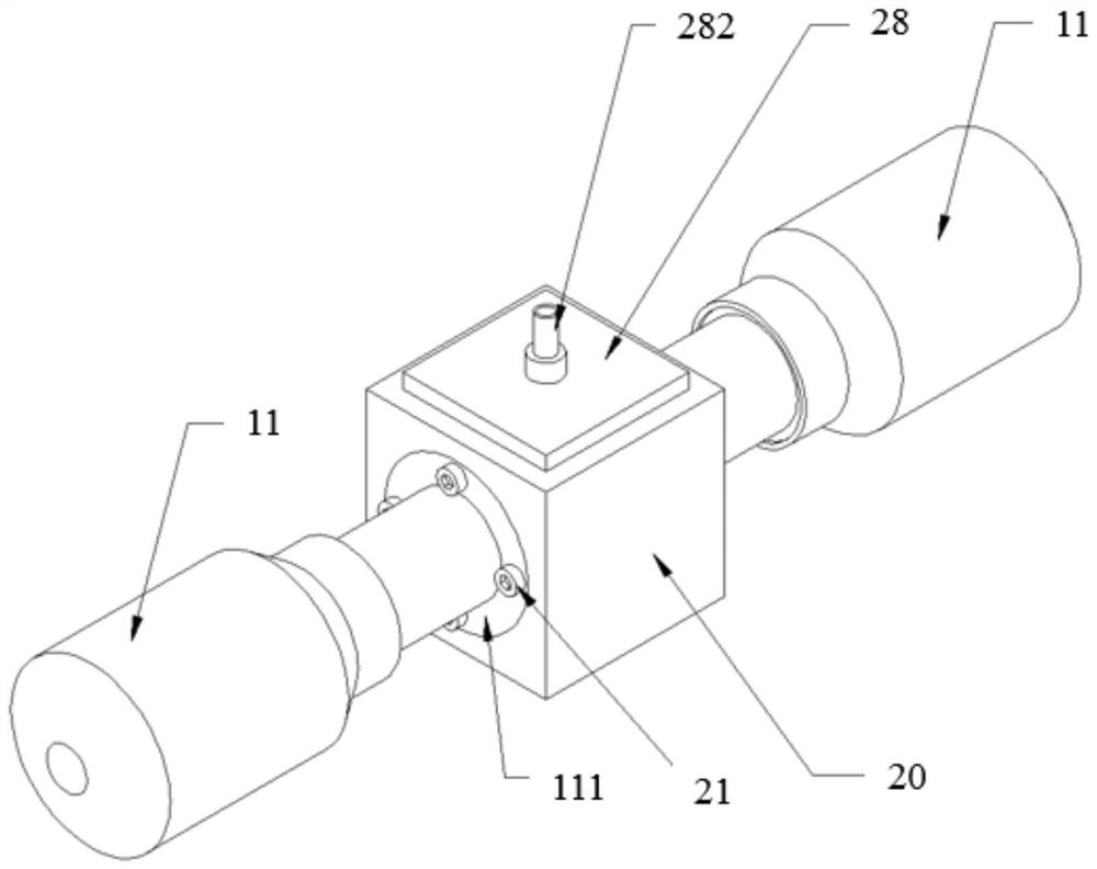
[0026] The refrigeration unit 10 includes at least two symmetrically arranged Stirling refrigerators 11 . In this embodiment, the number of Stirling refrigerators 11 is two. In practical applications, it may also be set as four Stirling refrigerators arranged symmetrically according ...


PUM


Abstract

The invention provides a refrigerated box device, comprising: a cooling part, used to generate cooling capacity, including at least two symmetrically arranged refrigerators; a certain amount of brine; the brine pump communicates with one end of the cold guide part and is used to provide brine; and the box body of the refrigerator includes an accommodating chamber and a serpentine coil, and the accommodating chamber is used for accommodating items to be refrigerated. The serpentine coil is used for the flow of the refrigerant and supplies the cold energy to the items to be refrigerated. The cooling part includes: the cooling shell, the cooling unit, multiple sets of cooling channels, the liquid separation tank and the liquid collection tank, and the cooling shell The two sides of the two refrigerators are respectively connected to two refrigerators; the cooling unit is set in the cooling shell and is in contact with the Stirling refrigerator to take away the cold; multiple sets of cooling channels are set in the cooling cavity and are cooled by the cooling block Surrounded, one end communicates with the liquid separation tank, and the other end communicates with the serpentine coil in the refrigerator box to transmit the cold energy to the refrigerator box.

Description

technical field [0001] The invention relates to the technical field of refrigeration and refrigeration, in particular to a refrigerator device. Background technique [0002] In recent years, with the rapid development of biology, pharmacy, medical and other fields, the demand for low-temperature refrigerators has been increasing year by year. As a small low-temperature regenerative refrigerator, the Stirling refrigerator has the characteristics of high efficiency at low temperature, no refrigerant pollution, wide cooling temperature range, low starting current, and easy adjustment of cooling capacity, so it is used as a small-capacity low-temperature refrigeration The cold source of the box has considerable advantages. [0003] However, in the mobile cold chain box in the prior art, a cold end adapter is provided outside the cold end of the Stirling refrigerator, and the cold end adapter is combined with the cold guide tube to transfer the cold energy of the Stirling refrig...

Claims


Application Information

Patent Timeline
Patent Type & Authority Patents(China)
IPC IPC(8): F25D19/04F25B41/00F25B9/14F25B41/40
CPCF25B9/14F25B41/00F25D19/04F25B2500/13
Inventor 陈曦缪源凌飞崔浩何韩军张华
Owner UNIV OF SHANGHAI FOR SCI & TECH
Learn More