Intelligent variable frequency control system of oil extractor

A technology of frequency conversion control and intelligent controller, which is applied in the direction of electrical program control, program control in sequence/logic controller, and production fluid, etc., which can solve the problems of increasing oil production cost, inability to supply liquid volume, pumping out, etc., and achieve improvement The effect of work efficiency, energy consumption minimization and output maximization

Inactive Publication Date: 2010-03-17
大连金光节能机电技术有限公司
View PDF0 Cites 11 Cited by
  • Summary
  • Abstract
  • Description
  • Claims
  • Application Information

AI Technical Summary

Problems solved by technology

However, as the production time increases and the reservoir pressure further decreases, at this time, the clogging of voids in the reservoir structure will slow down the seepage process, so that sufficient liquid cannot be supplied to the bottom of the production well
Although secondary oil recovery technology and tertiary oil recovery technology have been adopted, 60% to 70% of the crude oil in the structure cannot be recovered, and the seepage velocity can never return to the original level. At this time, the excessive pumping capacity and well The low liquid supply capacity leads to contradictions, and the specific reflection is the "pumping out" phenomenon, which directly affects the efficiency of the rod pump pumping system and increases the cost of oil production
At present, some rod pump pumping systems are also equipped with a frequency converter connected to the pumping unit, which can artificially judge the liquid volume at the bottom of the oil well and adjust the operating frequency of the pumping unit, but it cannot control the operation of the pumping unit. The state is monitored in real time, and then intelligent control is realized, so that there will be a phenomenon of "pumping out", which cannot fundamentally solve the problem

Method used


Image

  • Intelligent variable frequency control system of oil extractor

Examples


Embodiment Construction

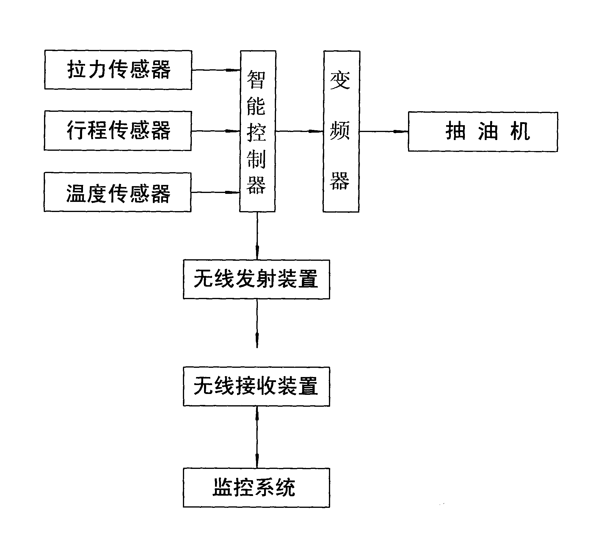
[0009] The specific implementation manner of the present invention will be described below with reference to the accompanying drawings. Such as figure 1 Shown: be provided with the frequency converter that joins with pumping unit the same as prior art, be connected with frequency converter with intelligent controller (microprocessor) differently with prior art, in the oil pumping unit of pumping unit A sucker rod pressure sensor and a sucker rod stroke sensor (rotary encoder) are arranged on the rod, and the sucker rod pressure sensor and the sucker rod stroke sensor are connected with an intelligent controller. The pressure sensor of the sucker rod automatically records the tension weight of the sucker rod, which provides data for the intelligent controller to measure the liquid level; Data; a temperature sensor can be installed next to the oil well or on the sucker rod to provide temperature data for the smart sensor. The intelligent controller interprets the data provided...


PUM


Abstract

The invention discloses an intelligent variable frequency control system of an oil extractor, which is provided with a frequency converter connected with the oil extractor, an intelligent controller connected with the frequency converter, an oil extracting rod pressure sensor and an oil extracting rod stroke sensor, wherein outputs of the oil extracting rod pressure sensor and the oil extracting rod stroke sensor are connected with the intelligent controller. The plurality of sensors and the intelligent controller can be used for monitoring the comprehensive situation of down-hole oil depositin a dynamic way, and a corresponding command signal can be sent to the oil extractor in time, so that the actual working state of the oil extractor can be ensured to be matched with the actual osmotic quantity of the down-hole oil deposit, and the aim of rapidly extracting when more oil exists, slowing extracting when less oil exists and not extracting when no oil exists; therefore, the state ofevacuation can be prevented, maximized yield and minimized consumption can be realized, the working efficiency of the oil extractor is effectively improved, and the oil extraction running cost is reduced.

Description

Technical field: [0001] The invention relates to a control device for a pumping unit, in particular to an intelligent frequency conversion control system for the pumping unit which can realize intelligent control of the pumping unit according to the tension, stroke and ambient temperature of the sucker rod. Background technique: [0002] Oil reservoirs, oil wells and surface facilities constitute the oilfield production engineering system. Initially, crude oil was produced by self-spraying of the reservoir's own energy. As the reservoir pressure decreased, artificial lift methods had to be used. Rod pump pumping system is the main oil production tool of the artificial lift method at present, and its efficiency is generally expressed by the percentage of useful work done by the system and the total energy consumed by the system (the total energy consumed by the system includes the electric energy of the entire system and related labor costs). In the early and middle stages ...

Claims


Application Information

Patent Timeline
Patent Type & Authority Applications(China)
IPC IPC(8): G05B19/04E21B43/00
Inventor 刘晓辉王东
Owner 大连金光节能机电技术有限公司
Why Eureka
Try Eureka