Backlight source lamp group
A technology of backlight source and lamp group, applied in the direction of light source, point light source, fixed light source, etc., can solve the problem of obvious heating phenomenon, without considering how to effectively use the heat energy of LED backlight source, etc., to achieve the effect of improving luminous intensity
- Summary
- Abstract
- Description
- Claims
- Application Information
AI Technical Summary
Problems solved by technology
Method used
Image

Examples
Embodiment 1
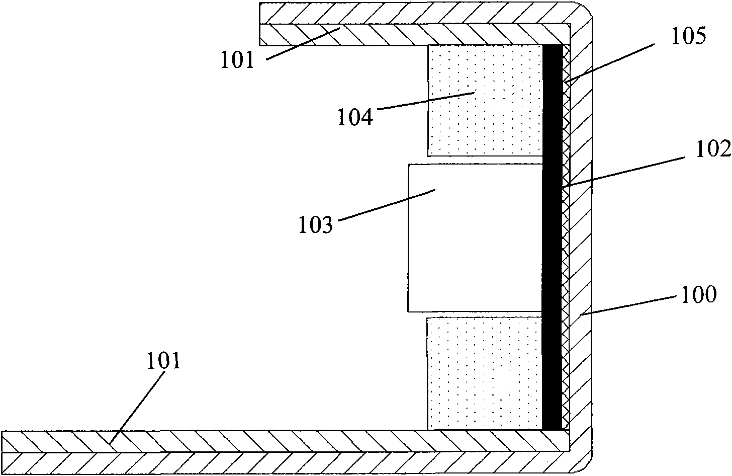
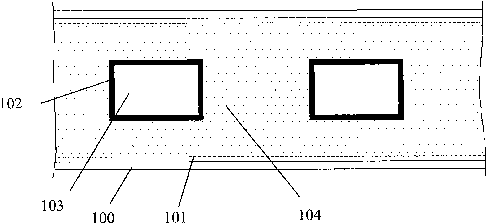
[0018] figure 1 with figure 2 All shown are schematic structural diagrams of the LED side-entry backlight lamp group of the embodiment of the present invention; it can be seen from the figure that the LED side-entry backlight lamp group includes: lampshade 100, reflective film 101, circuit board 102, LED 103 and a thermoluminescent material layer 104; a reflective film 101 and a circuit board 102 are pasted inside the lampshade 100, and the circuit board 102 is pasted in the lampshade 100 through a thermally conductive adhesive 105; LED 103 is arranged on the circuit board 102, and the circuit board A thermoluminescent material layer 104 is provided on the side of the LED 102 provided with the LED 103, and a through hole corresponding to the LED 103 is provided on the thermoluminescent material layer 104, and the LED 103 passes through the through hole.
[0019] The thermoluminescent material contained in the thermoluminescent material layer 104 uses alkaline earth sulfide a...
Embodiment 2
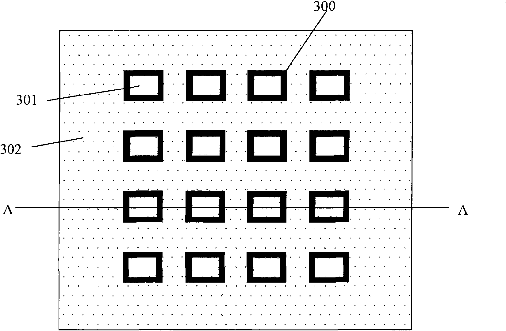
[0030] image 3 with Figure 4 All shown are schematic structural diagrams of the LED direct-lit backlight lamp group according to the embodiment of the present invention; it can be seen from the figure that the LED side-type backlight lamp group includes: a circuit board 300, an LED 301, and a thermoluminescent material layer 302 LED 301 is provided on the circuit board 300, and a thermoluminescent material layer 302 is provided on the side where the LED 301 is provided on the circuit board 300, and the circuit board 300 and the thermoluminescent material layer 302 are fastened on the back panel of the display and Between the frames, and between the circuit board 300 and the backplane are bonded by thermally conductive glue 304; a through hole corresponding to the LED 301 is provided on the thermoluminescent material layer 302, and the LED 301 passes through the through hole.
[0031] The material selected for the thermoluminescent material layer 302 and the preparation meth...
Embodiment 3
[0035] For backlights that use monochromatic LEDs and corresponding phosphors to produce white light, blue LEDs and yellow phosphors are commonly used in the prior art to produce white light. The luminescent material layer utilizes the thermal energy generated by the LED.
PUM
 Abstract
Description
Claims
Application Information
 - Generate Ideas
- Intellectual Property
- Life Sciences
- Materials
- Tech Scout
- Unparalleled Data Quality
- Higher Quality Content
- 60% Fewer Hallucinations
Browse by: Latest US Patents, China's latest patents, Technical Efficacy Thesaurus, Application Domain, Technology Topic, Popular Technical Reports.
© 2025 PatSnap. All rights reserved.Legal|Privacy policy|Modern Slavery Act Transparency Statement|Sitemap|About US| Contact US: help@patsnap.com