Polishing apparatus and polishing method
A technology for grinding devices and components, which can be used in grinding machines, belt grinders, grinding/polishing equipment, etc., and can solve the problems of larger reels, unstable grinding process, and larger influence of substrates.
- Summary
- Abstract
- Description
- Claims
- Application Information
AI Technical Summary
Problems solved by technology
Method used
Image
Examples
experiment example 1
[0080] In this experiment, the influence of the thickness of the hard part on the grinding results was investigated.
[0081] The experiment was performed under the following conditions.
[0082] The diameter of the abrasive grain (diamond grain) of the grinding tape: 5 μm (#4000)
[0083] The thickness of the base material of the abrasive belt: 25 μm
[0084] Hard parts: PET
[0085] Elastic parts: silicon sponge hardness 30 degrees
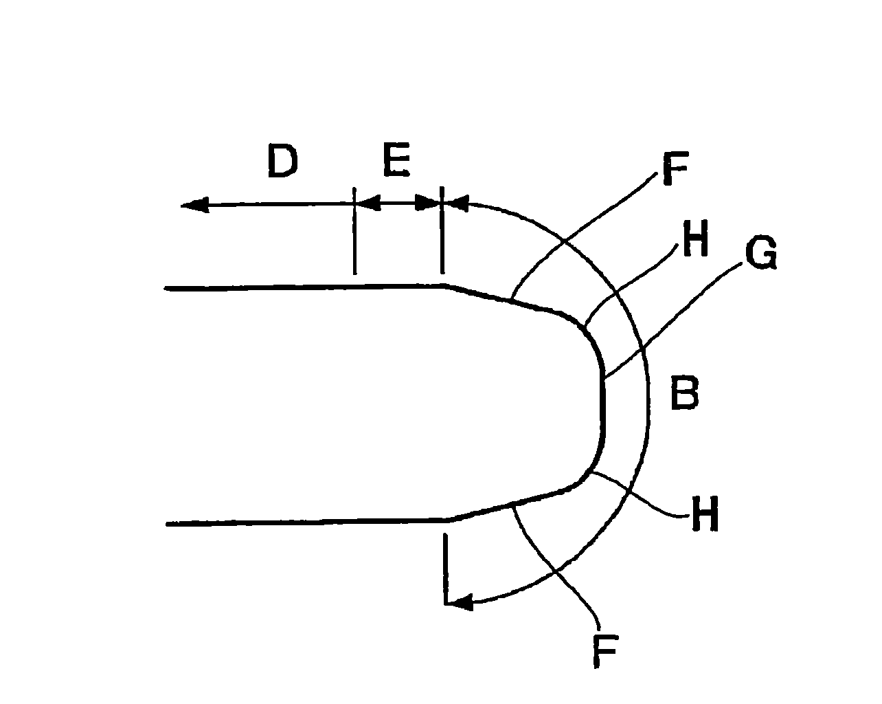
[0086] Under the above-mentioned conditions, experiments were performed by changing the thickness of the hard member within a range from 25 μm to 100 μm. According to the experimental results, when the thickness of the hard part is the thinnest 25 μm, the boundary part is ground faster than the central part, and as the hard part becomes thicker, the central part of the groove part becomes easier to be ground. grind. On the other hand, when the hard member becomes thicker, the contact area of the polishing tape with the wafer W becomes sma...
experiment example 2
[0090] In this experiment, the influence of the diameter of the abrasive grain of a grinding|polishing belt on a grinding|polishing result was investigated. Specifically, in Experimental Example 1, an experiment was conducted using a polishing tape with an abrasive grain diameter of 0.2 μm (#10000) and a base material thickness of 50 μm under the condition that both the polishing position controllability and the polishing speed gave good polishing results. As a result, it was confirmed that the polishing position controllability decreased. This is because when the diameter of the abrasive grains of the polishing tape is small, the polishing force becomes low, and the polishing surface of the polishing tape cannot reach the central portion. On the other hand, as in Experimental Example 1, when the diameter of the abrasive grains of the grinding belt is large, the grinding force is high, so even if the grinding surface of the grinding belt is only in contact with the boundary po...
experiment example 3
[0093] In this experiment, the influence of the hardness of the elastic member on the grinding result was investigated. Specifically, a polishing tape having an abrasive particle diameter of 0.2 μm (#10000) and a substrate thickness of 50 μm was used, and a PVC sheet with a thickness of 0.5 mm was used as a hard member. In addition, experiments were performed by changing the hardness and structure of the elastic member. That is, the sponge with a hardness of 30 degrees ( figure 1 5), a sponge with a hardness of 10 degrees (the method in Fig. 15), an elastic member filled with pure water (the method in Fig. 18), and an elastic member of the airbag type in which pressurized air is enclosed (the method in Fig. 19) , used as an elastic component for experiments.
[0094] As a result, changing the hardness of the sponge from 30 degrees to 10 degrees makes it easier for the hard member to follow the circumferential direction of the wafer, so the polishing rate increases. The ela...
PUM
| Property | Measurement | Unit |
|---|---|---|
| particle diameter | aaaaa | aaaaa |
| hardness | aaaaa | aaaaa |
| hardness | aaaaa | aaaaa |
Abstract
Description
Claims
Application Information
 - Generate Ideas
- Intellectual Property
- Life Sciences
- Materials
- Tech Scout
- Unparalleled Data Quality
- Higher Quality Content
- 60% Fewer Hallucinations
Browse by: Latest US Patents, China's latest patents, Technical Efficacy Thesaurus, Application Domain, Technology Topic, Popular Technical Reports.
© 2025 PatSnap. All rights reserved.Legal|Privacy policy|Modern Slavery Act Transparency Statement|Sitemap|About US| Contact US: help@patsnap.com


