Reinforced concrete structure or steel-concrete combined structure system

A reinforced concrete and composite structure technology, applied in the direction of building structure, construction, etc., can solve the problems of increasing structural weight and rigidity, increasing earthquake action, hidden safety hazards, etc., to achieve the protection of people's life and property safety, strong energy consumption capacity of the structure, Reasonable effect of force transmission

Inactive Publication Date: 2011-08-10
马文旭
View PDF0 Cites 0 Cited by
  • Summary
  • Abstract
  • Description
  • Claims
  • Application Information

AI Technical Summary

Problems solved by technology

[0003] According to the research results of relevant experts and scholars, the rigidity of the floor slab is very high, the beams and slabs are equipped with steel bars, and the bending resistance of the floor slab is also very large. However, the design of the building structure does not take into account the bending bearing capacity of the floor slab. The building structure design carried out in my country's relevant structural design codes actually did not meet the result of "strong columns and weak beams" required by the codes, which has great potential safety hazards
The survey results of the Wenchuan Earthquake show that for structures with frame components (frame structure, frame-shear wall structure, frame-tube structure), under the action of earthquakes, the structure is mainly damaged at the end of the column, but rarely at the end of the beam. Destruction, a large number of buildings collapsed due to column damage, resulting in huge loss of life and property, the buildings did not really achieve "strong columns and weak beams", which did not meet the spiritual requirements of the code
[0004] Therefore, to achieve "strong column and weak beam" with the current structural form, it is necessary to greatly increase the cross-sectional size of the column and the amount of reinforcement to balance the bending resistance of the floor slab, but at the same time it brings the following problems: (1) greatly Increase the cost of the building; (2) affect the use of the building and reduce the effective use area; (3) increase the weight and rigidity of the structure, and further increase the earthquake effect, and quite a few columns even become short columns, further increasing the building cost

Method used


Image

  • Reinforced concrete structure or steel-concrete combined structure system
  • Reinforced concrete structure or steel-concrete combined structure system
  • Reinforced concrete structure or steel-concrete combined structure system

Examples


Embodiment 1

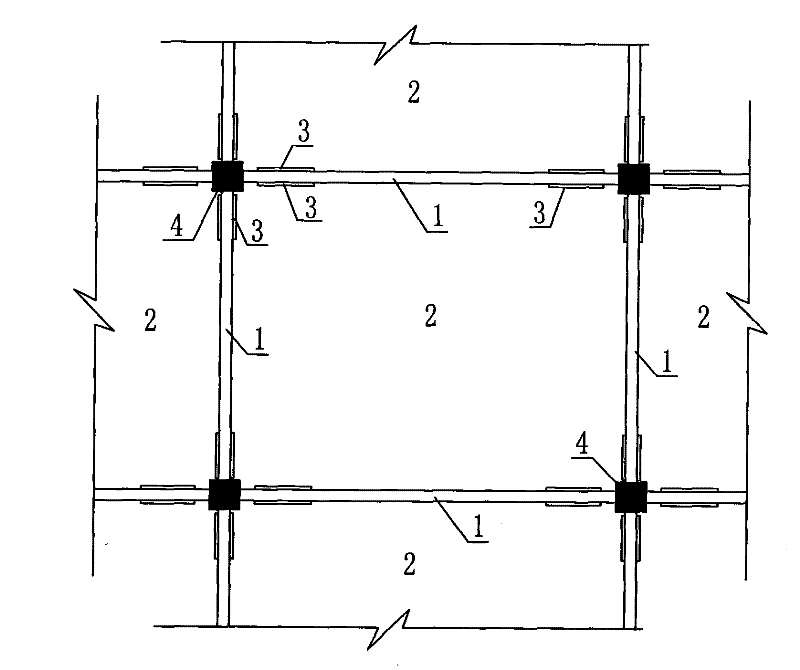
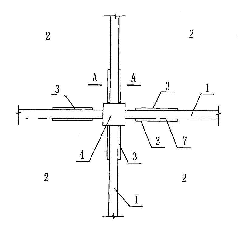
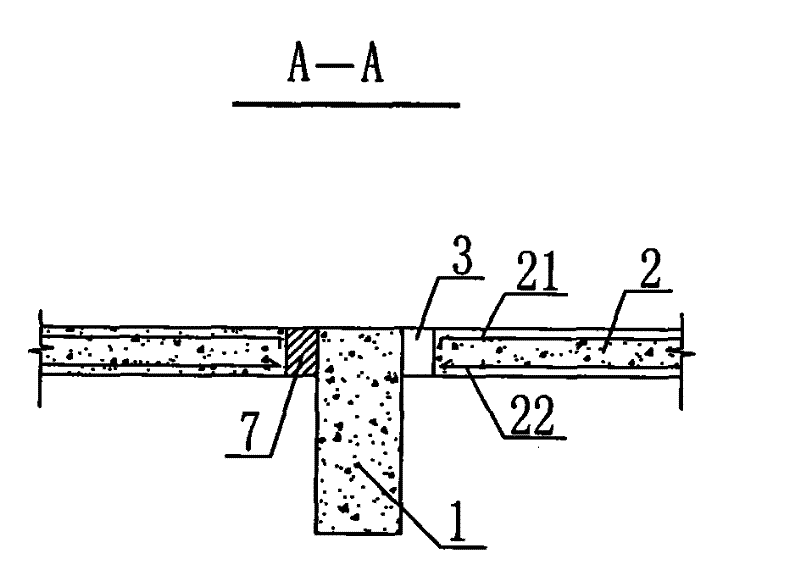
[0027] Such as Figure 1 to Figure 3 As shown, it is a schematic diagram of the structure of the present invention applied to the reinforced concrete frame structure system. At the near connection node of the beam 1 and the column 4, a rectangular opening 2 is opened on both sides of the beam 1, and the rectangular opening 2 is 5 away from the column. The side is 0-300mm, the width of the rectangular opening 2 is preferably 50-100mm, and the length is about L / 6 (L is the span of the beam), and it is greater than 300mm. 3, that is, there is no stressed reinforcement in floor 2. And the flexible material 7 is filled in the rectangular hole 3, and the flexible material 7 plays the role of waterproof and sound insulation.

[0028] Since the stress on the floor 2 is generally not large, most of them are structural reinforcements. After the rectangular opening 3 is set, the bearing capacity of the floor 2 can be realized by strengthening the reinforcement of other parts. After the...

Embodiment 2

[0030] Such as Figure 4 As shown, it is a schematic diagram of the structure of the present invention applied in the frame-shear wall structure system, which is at the connection node between the beam 1 and the column 4, and the connection between the beam 1 and the shear wall 5, on both sides of the beam 1 Rectangular hole 3 is all established, and all the other are with embodiment 1.

Embodiment 3

[0032] Such as Figure 5 As shown, it is a schematic diagram of the structure of the present invention applied in the shear wall structure system. At the joint between the shear wall 5 and the beam 1, rectangular openings 3 are set on both sides of the beam 1, and the rest are the same as in Embodiment 1.


PUM


Abstract

The invention discloses a reinforced concrete structure or a steel-concrete combined structure system, and aims to provide an earthquake-proof structure system capable of improving the earthquake-proof performance of a building structure and realizing strong columns and weak beams. The key point of the system comprises a vertical bearing structure, a beam connected with the vertical bearing structure and a floor slab connected with the vertical bearing structure and the beam, wherein a connection part or a near connection part of the beam and the vertical bearing structure is provided with a hole for locally separating the beam and the floor slab; and the beam end is a non T-shaped section beam which weakens the restraint effect of the floor slab on the beam, and the position for controlling the occurrence of a plastic hinge of the beam is positioned at the beam end so as to ensure the implementation of the strong columns and the weak beams. The system has reasonable force transfer, does not influence the bearing capacity of the floor slab, and is convenient to construct; and the manufacturing cost of the engineering is declined a little. The system has strong structural energy dissipation capacity, remarkably improves the ductility of structural objects, prevents the building from collapsing under the action of earthquake, and effectively protects the safety of human life andproperty.

Description

technical field [0001] The invention relates to a building structure system, more specifically, it relates to a reinforced concrete structure or a steel-concrete composite structure system applied in construction engineering. Background technique [0002] In the current reinforced concrete structure or steel-concrete composite structure system, there are frame structure, shear wall structure, frame-shear wall structure, frame-tube structure, tube structure, and tube-in-tube structure. The interconnection of each component of the above-mentioned various structures adopts rigid connection. It is a rigid lateral force resistant system. [0003] According to the research results of relevant experts and scholars, the rigidity of the floor slab is very high, the beams and slabs are equipped with steel bars, and the bending resistance of the floor slab is also very large. However, the design of the building structure does not take into account the bending bearing capacity of the f...

Claims


Application Information

Patent Timeline
Patent Type & Authority Patents(China)
IPC IPC(8): E04B1/20E04B1/21E04B1/30
Inventor 马文旭陆观宏
Owner 马文旭
Why Eureka
Try Eureka