
Load-reducing device for sintered material bed, sintering machine and sintering method using the same

A load-reducing device and sintering material technology, which is applied in lighting and heating equipment, furnace types, furnaces, etc., can solve the problems of poor load-reducing effect, inconvenient replacement, high cost, etc., and achieve improved air permeability, reduced use quantity, and small weight Effect

Active Publication Date: 2012-02-15
UNIV OF SCI & TECH BEIJING
View PDF12 Cites 0 Cited by
  • Summary
  • Abstract
  • Description
  • Claims
  • Application Information

AI Technical Summary

Problems solved by technology

However, this type of load-reducing plate has disadvantages such as poor load-reducing effect, easy damage, inconvenient replacement, and high cost.

Method used


Image

  • Load-reducing device for sintered material bed, sintering machine and sintering method using the same
  • Load-reducing device for sintered material bed, sintering machine and sintering method using the same
  • Load-reducing device for sintered material bed, sintering machine and sintering method using the same

Examples


Embodiment Construction

[0025] The present invention will be described in detail below with reference to the accompanying drawings. It should be understood by those skilled in the art that the following embodiments are only for illustration purposes, and are not intended to limit the present invention.

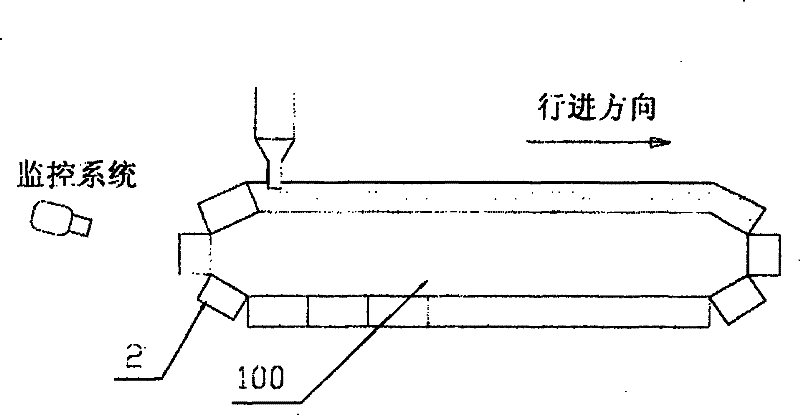
[0026] like figure 1 As shown, a belt sintering machine generally indicated as 100 includes a plurality of trolleys 2 with bottoms for carrying sintering raw materials 10 (see Figure 4 ), and the sintering raw material 10 is transported to the discharge side (right side in the figure) after being sintered from the feed side (left side in the figure) of the sintering machine. A monitoring system or monitoring system is provided on the feeding side of the sintering machine 100, and its purpose will be described in detail below.

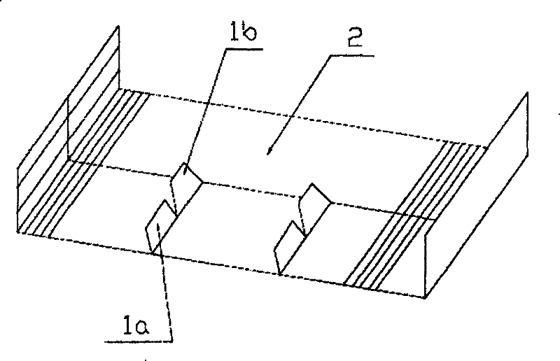
[0027] like figure 2 As shown, trolley 2 moves along its direction of travel ( figure 1 and Figure 4 In the direction of the arrow shown), there are multiple rows of s...


PUM


Abstract

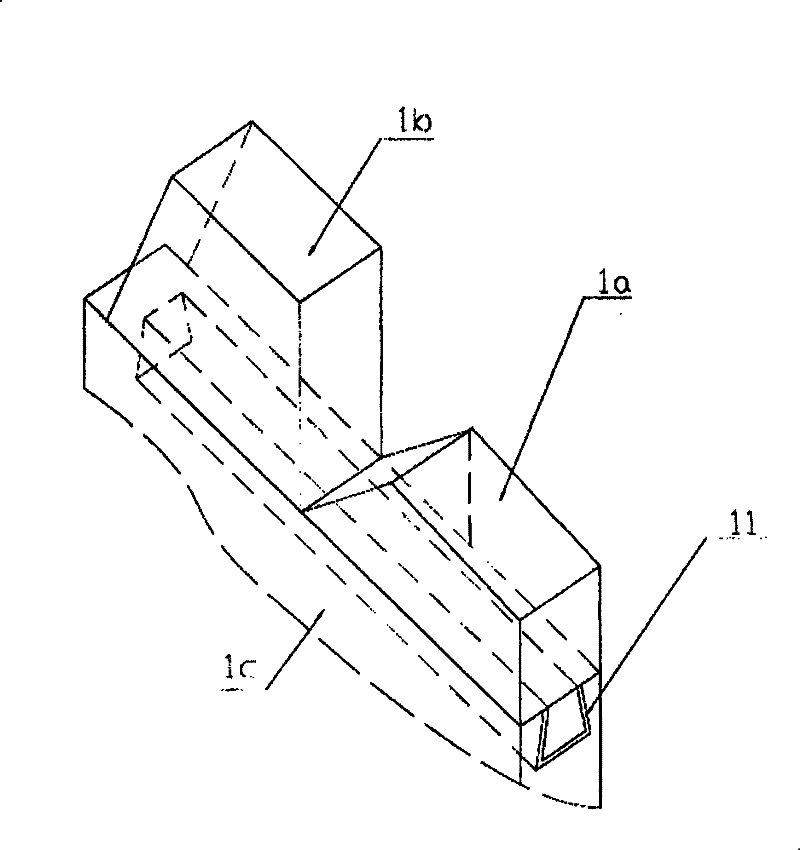
A load-reducing device for a sintered bed, a sintering machine using the device and a sintering method. The load-reducing device for the sintering material layer includes: a strip-shaped base, which is configured to be installed on the bottom of the sintering machine trolley parallel to the traveling direction of the sintering machine trolley; It is detachably installed on the base, wherein adjacent right-angle trapezoidal load-relief plates are not adjacent to each other with right-angle sides. The structure of the unloading device can greatly increase its effective supporting area without increasing the overall weight of the unloading device. In addition, because the load-relief device can be, for example, three-piece, the weight of each single piece is small, and it is easy to assemble and disassemble. In addition, the material of each part can be different, thereby reducing the manufacturing cost.

Description

technical field [0001] The present invention relates to a sintering machine, in particular to a sintering bed unloading device used in the sintering machine. Background technique [0002] According to the temperature and physical and chemical changes, the sintered material layer is generally divided into five zones from top to bottom: burnt ore zone, combustion melting zone, drying pre-tropical zone, moisture condensation zone and original sintered material zone. The resistance loss per unit height of the material layer is the largest in the drying preheating zone and the combustion melting zone. [0003] In the dry preheating zone, the wet bulb will break during drying and preheating, and at the same time, it will be affected by the pressure of the upper burnt belt material layer and the downward draft, making the material layer porosity smaller and resistance increased. [0004] In the combustion melting zone, the temperature is high, and there is liquid phase formation, ...

Claims


Application Information

Patent Timeline
Patent Type & Authority Patents(China)
IPC IPC(8): F27B21/08F27B21/14
Inventor 杨天钧张建良左海滨刘征建国宏伟
Owner UNIV OF SCI & TECH BEIJING
Learn More