Defect hole image recognition method

An image recognition and defect technology, applied in the field of defect hole image recognition, can solve problems such as complicated operation, and achieve the effect of improving accuracy, scientific method, simple and reliable equipment

Inactive Publication Date: 2010-04-14
郭震
View PDF0 Cites 19 Cited by
  • Summary
  • Abstract
  • Description
  • Claims
  • Application Information

AI Technical Summary

Problems solved by technology

The existing defect detection methods such as pinholes on the welding surface and pores on the casting surface mainly rely on the recognition of the human eye. For the internal pore defects that cannot be rec

Method used


Image

  • Defect hole image recognition method
  • Defect hole image recognition method
  • Defect hole image recognition method

Examples


Embodiment Construction

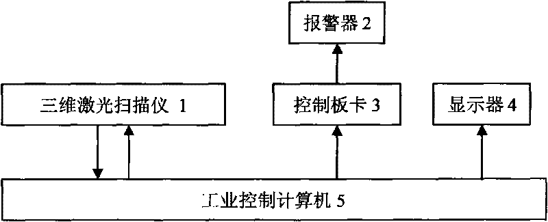
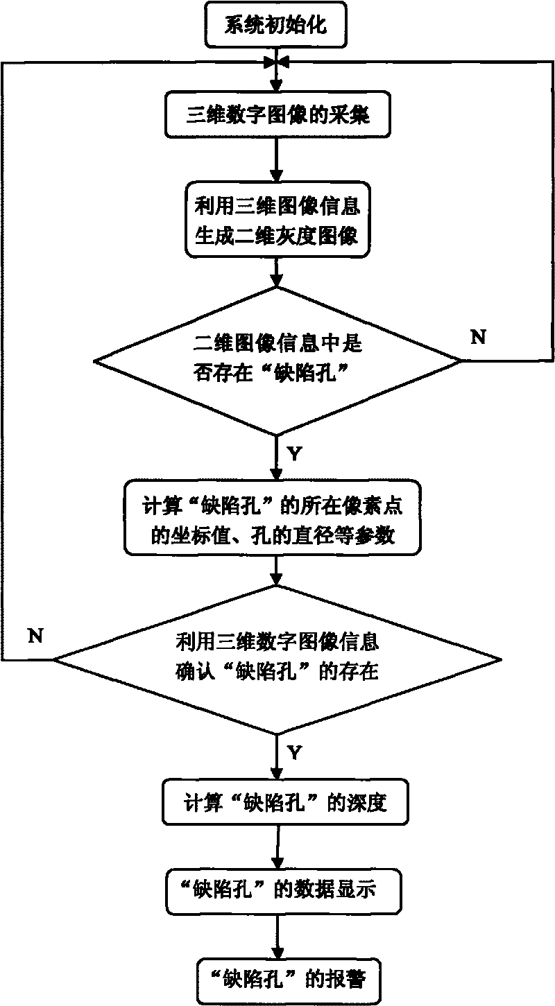
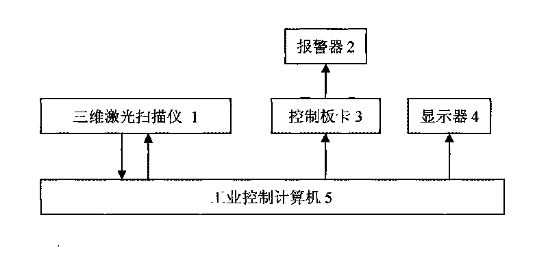
[0018] A defect hole image recognition method, the system adopted includes a three-dimensional laser scanner 1, an alarm 2, a control board 3, a display 4 and an industrial control computer 5, the three-dimensional laser scanner 1 is connected with the industrial control computer 5, and the three-dimensional laser The scanner 1 accepts the instruction of the industrial control computer 5 to collect the three-dimensional digital image information of the detected object, and transmits the obtained image information to the industrial control computer 5. The alarm 2 is connected with the industrial control computer 5 through the control board 3. When the system When it is detected that the defect hole exists, the relay on the control board 3 is energized, the alarm 2 is connected, the alarm 2 sends an alarm, the display 4 is connected with the industrial control computer 5, and receives signals from the industrial control computer 5 for Display relevant data and image information o...


PUM


Abstract

The invention relates to a defect hole image recognition method which comprises the following steps: firstly, a defect hole is preliminarily judged by adopting a grayscale image processing technology according to the grey value characteristic of a defect hole image, and local coordinate of the possible defect hole is found out; and then the existence of the defect hole is further determined by applying a three-dimensional digital image technology according to the data characteristic of the defect hole in a three-dimensional image, and parameters such as the position, size, depth and the like of the defect hole are calculated. Compared with the prior art, the defect hole image recognition method has the following advantages: the accuracy of defect hole monitoring is higher; on the basis of a defect hole monitoring method for two-dimensional image information, information in the three-dimensional digital image is utilized for judgment and recognition, thus greatly improving the accuracy of the judgment and recognition; simultaneously, the two-dimensional and three-dimensional digital image technologies are adopted for realizing the online detection of the defect hole, with scientific, reasonable and accurate methods; real-time display and monitoring of data and signals of defect hole detection are realized; and applied devices are simple and reliable, and have cost advantage.

Description

technical field [0001] The invention relates to a defect hole image recognition method. Background technique [0002] During the processing of parts, such as welding, casting, injection molding, etc., the surface pores that affect the processing quality of parts are called defect holes. The existing defect detection methods such as pinholes on the welding surface and pores on the casting surface mainly rely on the recognition of the human eye. For the internal pore defects that cannot be recognized by the human eye, there are mainly magnetic particle testing, penetrant testing, ultrasonic testing and eddy current testing. Methods such as detection, these methods are very cumbersome to operate. Contents of the invention [0003] The object of the present invention is to provide a defect hole image recognition method capable of on-line detection, high accuracy and low cost. [0004] The defect hole image recognition method of the present invention first adopts the grayscal...

Claims


Application Information

Patent Timeline
IPC IPC(8): G01N21/88G01B11/00G01B11/22G06K9/00
Inventor 郭震郭厚焜
Owner 郭震
Why Eureka
Try Eureka