
Bridge monitoring system based on software bus platform

A monitoring system and soft bus technology, applied in the field of control, can solve problems such as high difficulty and high cost, and achieve the effects of convenient expansion, convenient networking, and high efficiency

Inactive Publication Date: 2010-04-14
邵鹏飞
View PDF1 Cites 6 Cited by
  • Summary
  • Abstract
  • Description
  • Claims
  • Application Information

AI Technical Summary

Problems solved by technology

However, based on the different technical interfaces of various existing bridge monitoring systems, it is very difficult and costly to directly interconnect or use some kind of hardware equipment to achieve interconnection

Method used


Image

  • Bridge monitoring system based on software bus platform
  • Bridge monitoring system based on software bus platform
  • Bridge monitoring system based on software bus platform

Examples


Embodiment 1

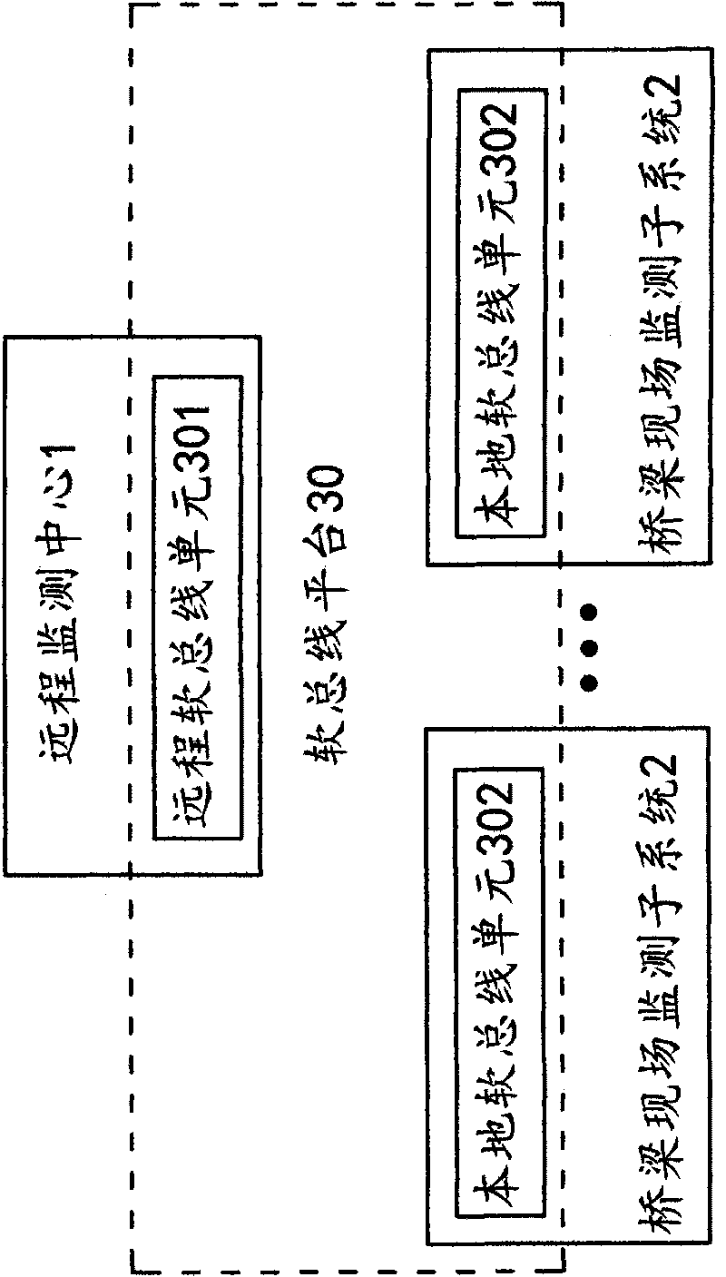
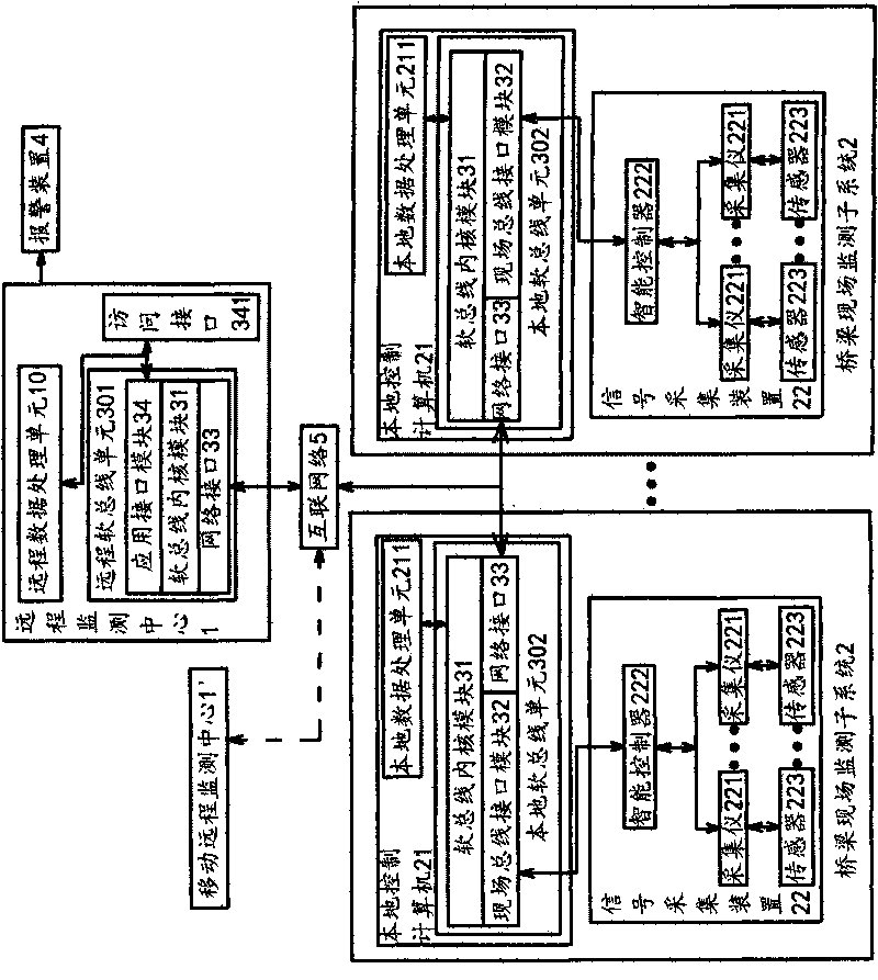
[0032] Such as figure 1 with 2 As shown, the bridge monitoring system based on the softbus platform includes a remote monitoring center 1 capable of data processing and at least one on-site bridge monitoring subsystem 2 . The remote monitoring center 1 has a remote data processing unit 10 . Here, bridge on-site monitoring subsystems 2 are set in one-to-one correspondence with bridges, and the number can be set according to needs, usually including multiple bridge on-site monitoring subsystems 2 on multiple bridges in a city or region. The bridge on-site monitoring subsystem 2 may be built, under construction, or not yet planned. Data processing includes parsing, storing, analyzing, displaying and other operations on the received data.

[0033] Each bridge site monitoring subsystem 2 includes a local control computer 21 and a signal acquisition device 22 connected to the local control computer 21 . The signal collection device 22 is connected to the bridge and can collect v...

Embodiment 2

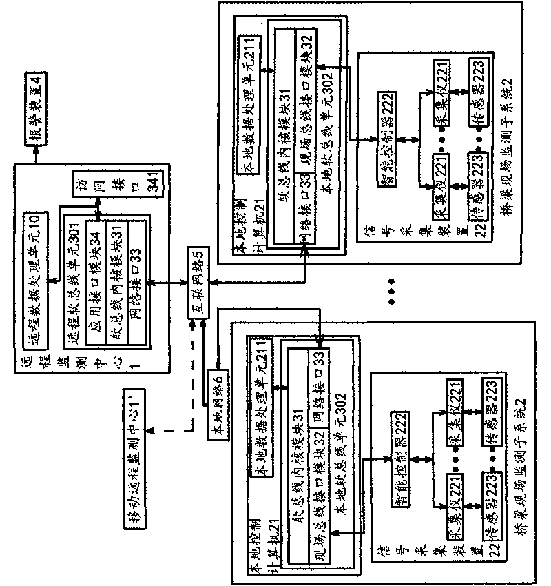
[0047] Such as image 3 As shown, in this embodiment, the sensor 223 is connected to the acquisition instrument 221 through a cable, and the acquisition instrument 221 is connected to the intelligent controller 222 using a field bus. The field bus can be various feasible buses such as RS485 bus or CAN bus. The uplink interface of the intelligent controller 222 is a standard network interface, through which the intelligent controller 222 is directly connected to the local network 6, and the communication protocol may adopt the ModBus / TCP protocol.

[0048] The local control computer 21 is also connected to the local network 6 through its standard network interface, is in the same network as the intelligent controller 222 , and can communicate with each other through the local network 6 . The local network 6 is interconnected with the Internet network 5 . Then establish a network connection with the remote monitoring center 1 or the mobile remote monitoring center 1' through th...


PUM


Abstract

The invention relates to a bridge monitoring system based on a software bus platform, which belongs to the technical field of control and solves the technical problems of unreasonable structure and the like of the prior art. The bridge monitoring system comprises a remote monitoring center and at least one bridge field monitoring subsystem; each bridge field monitoring subsystem respectively comprises a local control computer and a signal collecting device connected onto the local control computer; each signal collecting device connected onto a bridge is capable of collecting various physical quantity data of the bridge; the remote monitoring center is connected with each signal collecting device via the software bus platform; the software bus platform converts the data and enables the remote monitoring center and each signal collecting device to realize data exchange. The bridge monitoring system has the advantages that: 1 data communication between identical or different bridge field monitoring subsystems and the remote monitoring center is realized. 2 collection devices of the same bridge field monitoring subsystem work parallelly under the control of an intelligent controller. 3 not only local control and data collection, but also remote control and data collection can be realized.

Description

technical field [0001] The invention belongs to the technical field of control and relates to a monitoring system, in particular to a bridge monitoring system based on a soft bus platform. Background technique [0002] Due to factors such as climate, oxidation, corrosion or aging during the operation of the bridge, and long-term damage under the action of dead load or live load, its strength and stiffness will decrease with time, which not only affects safe driving, More can make the service life of this bridge shorten. Therefore, it is necessary to establish a bridge structure analysis, computer communication and network, modern sensor detection, monitoring technology, bridge evaluation and maintenance management on the basis of the existing technical level, based on monitoring, condition evaluation and bridge maintenance management. A health monitoring and evaluation system in various aspects is used to monitor and evaluate the operating status of bridges and provide a ba...

Claims


Application Information

Patent Timeline
IPC IPC(8): G05B19/048G05B19/418
CPCY02P90/02
Inventor 邵鹏飞张萱梁丰
Owner 邵鹏飞
Learn More