
Side transducer for detecting rolling pressure of rolling mill

A force measuring sensor and rolling pressure technology, applied in the control field of rolling mills, can solve the problems of high shear strength, large shrinkage rate, poor impact resistance, etc.

Inactive Publication Date: 2010-04-21
HUAIHAI INST OF TECH
View PDF0 Cites 16 Cited by
  • Summary
  • Abstract
  • Description
  • Claims
  • Application Information

AI Technical Summary

Problems solved by technology

For a certain adhesive, if its shear strength is high, the shrinkage rate will be large, and the impact resistance will be poor; if the toughness is good, the curing time will be long; the adhesive curing method used at high temperature, pasting The operation is more complicated
Therefore, this dynamometric error usually amounts to 10%

Method used


Image

  • Side transducer for detecting rolling pressure of rolling mill
  • Side transducer for detecting rolling pressure of rolling mill
  • Side transducer for detecting rolling pressure of rolling mill

Examples


Embodiment Construction

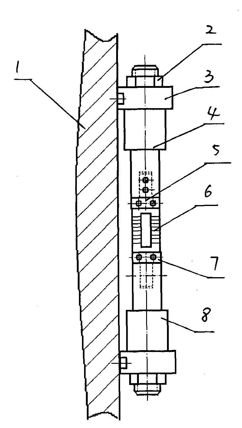
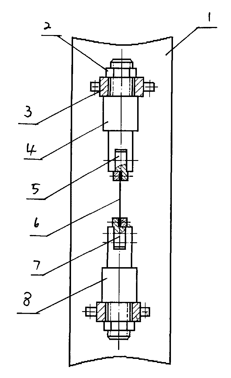
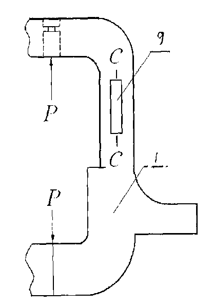
[0015] A side-mounted sensor 9 for detecting the rolling pressure of a rolling mill. A load cell 6 is arranged on the side of the frame column 1. The load cell 6 is vertically arranged along the center line of the frame column. The load cell 6 is determined by the thickness It is made of permalloy sheet of 0.3-0.6mm, and the permalloy sheet is vertically arranged with the frame column 1. There is a strip hole in the middle of the permalloy sheet, and the excitation coil N is wound on both sides of the strip hole. 1 and measuring coil N 2 , the two ends of the load cell are provided with upper and lower clamping heads 5,7, an insulating rubber pad is provided between the load cell 6 and the upper and lower clamping heads 5,7, and the upper and lower clamping heads 5,7 The upper and lower force transmission rods 4 and 8 are fixed by bolts, the upper and lower force transmission rods 4 and 8 respectively pass through the support 3 installed on the frame, and load cells are instal...


PUM

PropertyMeasurementUnit
Thicknessaaaaaaaaaa
Number of turnsaaaaaaaaaa

Abstract

The invention relates to a side transducer for detecting a rolling pressure of a rolling mill. A lateral surface of an upright post of a frame is provided with a force transducer. The force transducer is vertically arranged along a center line of the upright post of the frame. The force transducer is made of a permalloy sheet. The permalloy sheet is vertical to the upright post of the frame. The middle part of the permalloy sheet is provided with a strip hole. Both sides of the strip hole are wound by a magnet exciting coil and a measuring coil respectively. Both ends of the force transducer are provided with upper and lower clamping heads. The upper and lower clamping heads are fixed with force transmitting pull rods. The force transmitting pull rods pass through a support saddle of the frame respectively. End parts of the force transmitting pull rods are provided with force transducer pretightening force regulating nuts. Each force transmitting pull rod is a stepped shaft, and the diameter ratio of a small shaft end to a big shaft end is 1: 2-10. When the rolling mill carries out rolling, the upright post of the frame of the rolling mill generates elastic deformation under the action of a reaction force. The size of the elastic deformation is proportional to a rolling force. The rolling force can be calculated by measuring the strain of the upright post of the frame. The side transducer for detecting the rolling pressure of the rolling mill has the advantages of convenient installation and disassembly, high detection sensitivity and small error.

Description

technical field [0001] The invention relates to a control technology of a rolling mill, in particular to a side-mounted sensor for detecting rolling pressure of a rolling mill. Background technique [0002] At present, there are two main ways to detect the rolling force of domestic rolling mills: one is the supporting force measurement, that is, the sensor directly bears the measured force. The sensors used mainly include resistance strain type, inductive type, capacitive type, piezoelectric type and piezoelectric magnetic type. When in use, it is generally installed in the following three positions: (a) between the pressing screw and the bearing seat of the upper backup roller; (b) between the bearing seat of the lower backup roller and the lower beam of the frame archway; (c) pressing Between the lower nut and the upper beam of the rack archway. Because its force-bearing part-the pressure measuring head directly and frequently bears the rolling force, it is easy to be da...

Claims


Application Information

Patent Timeline
IPC IPC(8): B21B38/08G01L1/12G01L5/00
Inventor 石延平
Owner HUAIHAI INST OF TECH
Learn More