
Side braking ratchet wheel tension compensation device of electrization railway

A technology for electrified railways and brake ratchets, which is applied in the field of compensation devices for compensating the anchor tension of catenary cables and contact wires, and side brake ratchet tension compensation devices. The effect of avoiding locomotive interruption and reducing operating costs

Active Publication Date: 2011-09-07
SHAANXI FLYWHEEL HIGH SPEED RAIL EQUIP CO LTD
View PDF0 Cites 0 Cited by
  • Summary
  • Abstract
  • Description
  • Claims
  • Application Information

AI Technical Summary

Problems solved by technology

[0003] The purpose of the present invention is to provide a side brake ratchet tension compensation device for electrified railway catenary, which solves the existing radial brake ratchet compensation device, which is easy to hit and break teeth, and compensates for mutual extrusion and wear of steel wire ropes when they are wound. problem and does not require regular oil lubrication

Method used


Image

  • Side braking ratchet wheel tension compensation device of electrization railway
  • Side braking ratchet wheel tension compensation device of electrization railway
  • Side braking ratchet wheel tension compensation device of electrization railway

Examples


Embodiment Construction

[0022] The present invention will be described in detail below in conjunction with the accompanying drawings and specific embodiments.

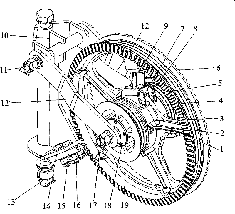
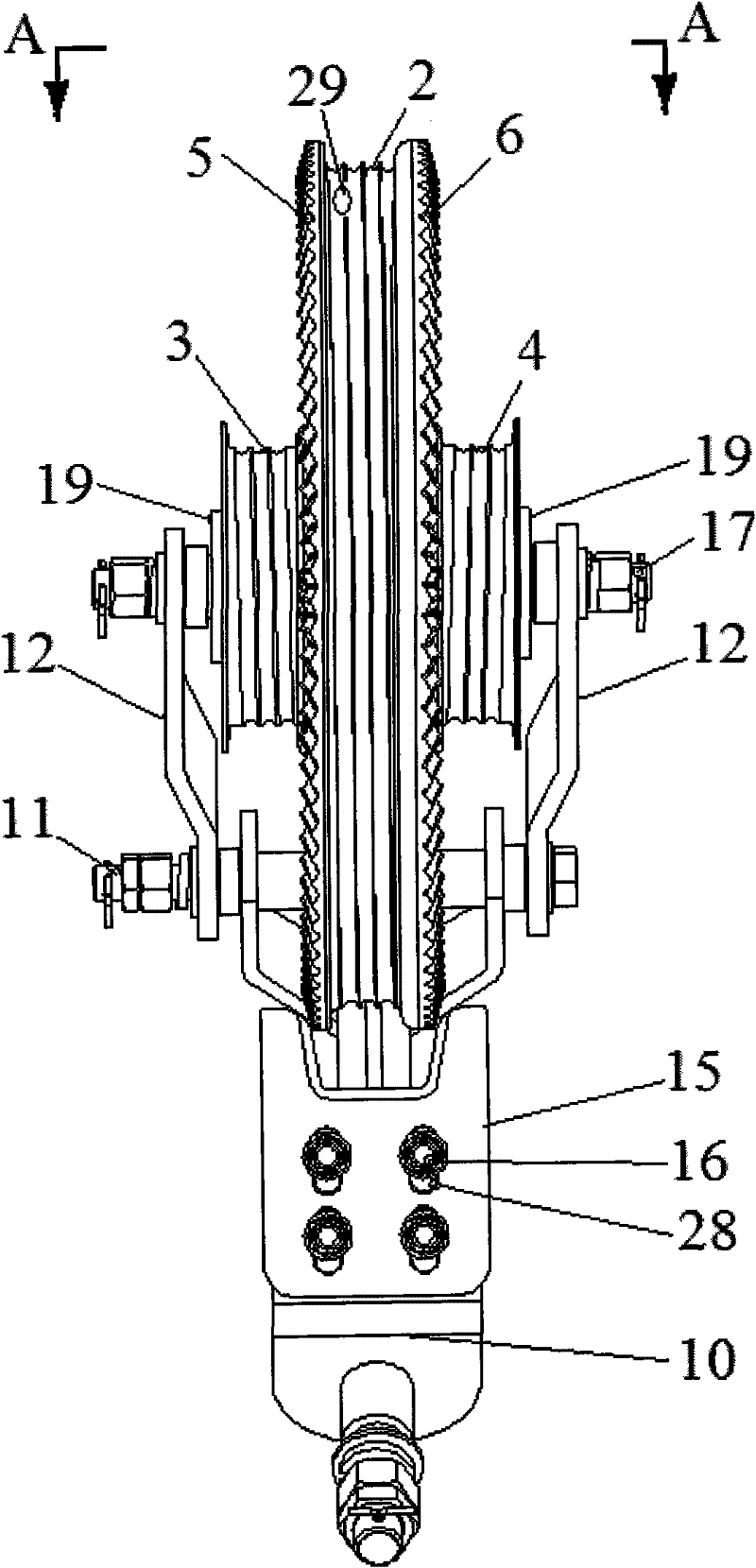
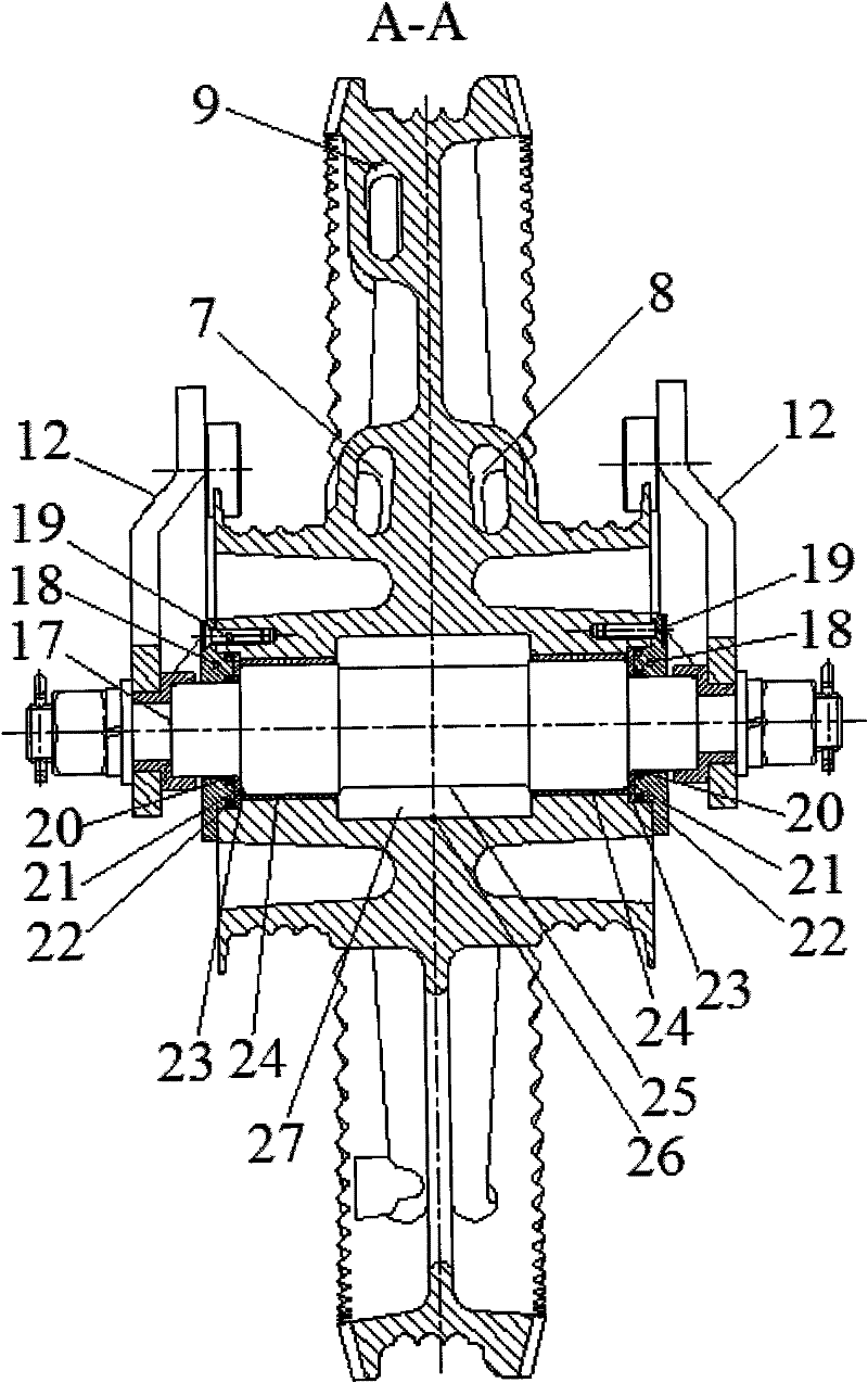
[0023] The structure of the side brake ratchet compensation device of the present invention, such as figure 1 , figure 2 , image 3 shown. Including a vertically arranged brake support frame 10, a bolt part A11 is arranged in the horizontal casing at the upper end of the brake support frame 10, and the bolts in the bolt part A11 pass through the horizontal casing, and the bolts are connected to one end of the two swing arms 12 respectively. The two swing arms 12 are respectively located at the two ends of the horizontal sleeve, and the other ends of the two swing arms 12 are respectively connected with the ratchet shaft 17. The ratchet shaft 17 is fixedly connected with the ratchet body 1, and the ratchet body 1 consists of a hub, a plurality of Composed of a spoke plate and a wheel rim, the two sides of the spoke plate of the ratchet bod...


PUM


Abstract

The invention relates to a side braking ratchet wheel tension compensation device of an electrization railway, comprising a braking support frame. The braking support frame is connected with a ratchet wheel shaft through two rotary arms; the ratchet wheel shaft and a ratchet wheel body are coaxially arranged through a sliding bearing made of self-lubricating composite material; the ratchet wheel body can rotate around the ratchet wheel shaft and consists of a hub, a plurality of radial plates and a wheel flange; a tension wheel groove A and a tension wheel groove B are respectively arranged at the two sides of the radial plates of the ratchet wheel body and the outer circumference surface of the hub; rope troughs are arranged in the two grooves; the outer circumference surface of the wheel flange is provided with a ratchet wheel trough the bottom of which is cast with a rope trough and a steel wire rope hole; braking gear rings are symmetrically cast on the two sides of the wheel flange; and the lower end of the braking support frame is fixedly connected with a buffer brake device. The invention is suitable for a working state that a carrier cable and a contact line slowly change under the influence of environment temperature, overcomes the defects of frequent off-line, arc discharge, burning of a contact line and the like of a pantograph of a locomotive, is free from oil injection and maintenance and has long service life.

Description

technical field [0001] The invention belongs to the technical field of catenary systems for electrified railway power supply equipment, and relates to a compensating device for compensating the anchor tension of a catenary cable and a catenary line, in particular to a side brake ratchet tension compensating device. Background technique [0002] The catenary cables and contact wires of the catenary system in electrified railway power supply equipment are affected by environmental and temperature changes, such as thermal elongation and cold contraction, which cause continuous changes in line tension. Although this change is very slow, it is enough to make the catenary line not work properly. In order to ensure the normal operation of the catenary line, the tension compensation device is used to eliminate the change of the catenary cable and the contact line with the temperature. At present, the radial braking ratchet tension compensation device used in the catenary has the fol...

Claims


Application Information

Patent Timeline
Patent Type & Authority Patents(China)
IPC IPC(8): B60M1/26
Inventor 舒文琛李霁开
Owner SHAANXI FLYWHEEL HIGH SPEED RAIL EQUIP CO LTD
Learn More