Axial flow compressor serially connected by multiple single-stage axial flow fans in L-shaped arrangement

A technology of axial flow compressors and axial flow fans, applied in the field of axial flow compressors, can solve problems such as the inability to arrange axial flow compressors, and achieve the effects of reducing design and manufacturing difficulty, ensuring reliability, and reducing length

Inactive Publication Date: 2010-04-21
SHANGHAI BLOWER WORKS
View PDF0 Cites 7 Cited by
  • Summary
  • Abstract
  • Description
  • Claims
  • Application Information

AI Technical Summary

Problems solved by technology

[0004] For closed-cycle wind tunnels, axial flow compressors are generally arranged between the first and second corners of the wind tunnel or after the second corner, but due to the limitation of the overall size of the wind tunnel, some relatively long axial flow compressors cannot be arranged

Method used


Image

  • Axial flow compressor serially connected by multiple single-stage axial flow fans in L-shaped arrangement
  • Axial flow compressor serially connected by multiple single-stage axial flow fans in L-shaped arrangement
  • Axial flow compressor serially connected by multiple single-stage axial flow fans in L-shaped arrangement

Examples


Embodiment 1

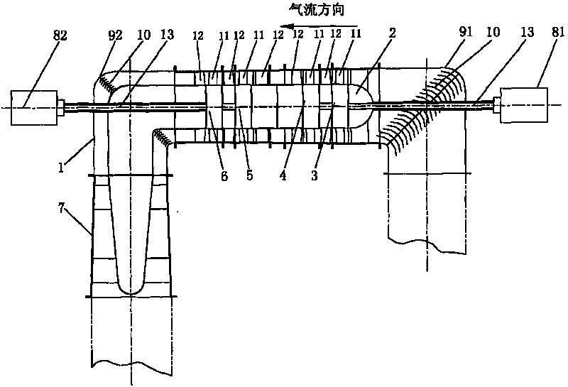
[0016] like figure 1 As shown, an axial flow compressor in which multiple single-stage axial flow fans arranged in an L shape are connected in series, including a casing 1, a fairing 2, an I-stage impeller 3, a II-stage impeller 4, a III-stage impeller 5, and an IV stage impeller 6 and diffuser 7, the casing 1 is an elongated pipe with two right-angled corners arranged along the airflow direction of the wind tunnel, the first corner 91 and the second corner 92 of the casing 1 are all installed There are turning guide vanes 10; the entire axial flow compressor is arranged in an L shape, the fairing 2 is installed behind the first corner 91, and the diffuser 7 is installed behind the second corner 92, and is located at the tail end of the casing 1; each stage The impellers respectively include a moving blade 11 and a guide vane 12. Along the direction of air flow, the guide vane 12 is arranged behind the moving blade 11. The inner diameter and blade installation angle of each mo...

Embodiment 2

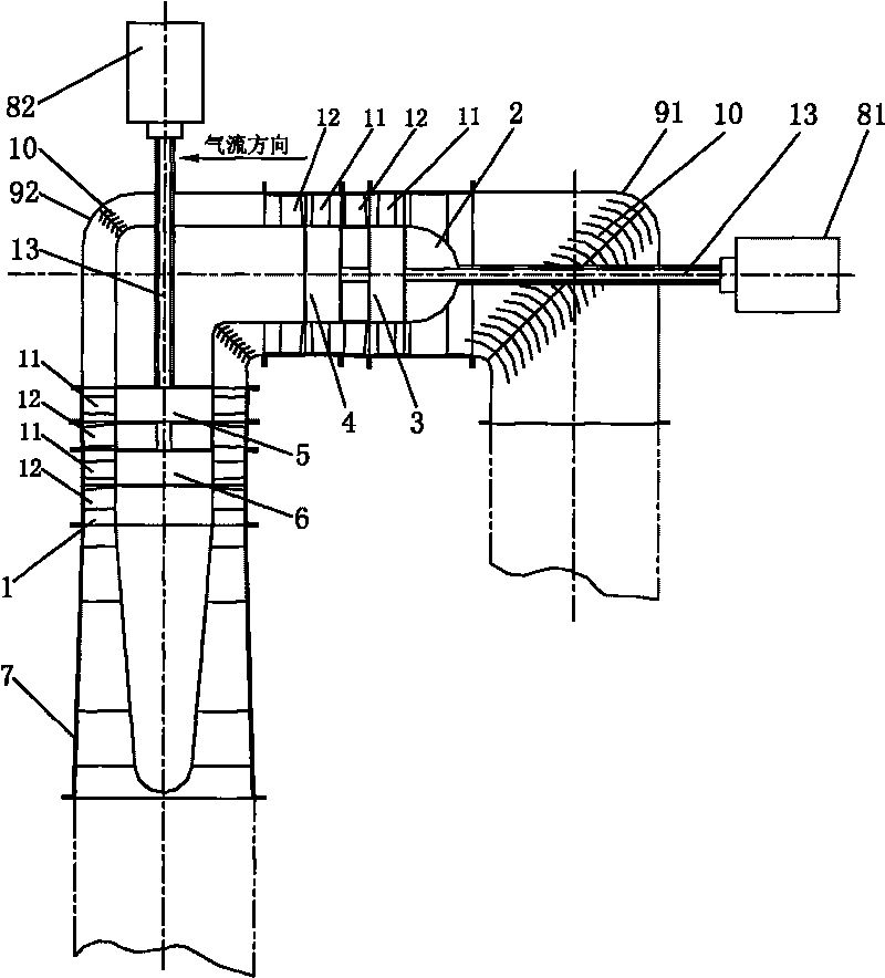
[0019] like figure 2 As shown, an axial flow compressor in which a plurality of single-stage axial flow fans arranged in an L shape are connected in series. The difference between embodiment 2 and embodiment 1 is that along the direction of air flow, the first-stage impeller 3 and the second-stage The impellers 4 are arranged coaxially in series between the first corner 91 and the second corner 92. The I and II stage impellers and the fairing 2 together form one side of the L shape. The III stage impeller 5 and the IV stage impeller 6 are connected in series. Arranged coaxially after the second corner 92 in sequence, the III and IV stage impellers and the diffuser 7 together form the other side of the L-shape; where the I-stage impeller 3 and the II-stage impeller 4 form a group and are connected to the first stage through the intermediate shaft 13 The main motor 81, the first main motor 81 is installed on the axial head of the I-stage impeller 3; the III-stage impeller 5 and...


PUM


Abstract

The invention relates to the field of fans used for closed type circular wind tunnels, in particular to an axial flow compressor formed by serially connecting by multiple fans, i.e. an axial flow compressor formed by serially connecting by multiple single-stage axial flow fans in L-shaped arrangement, comprising a casing, a fairing, an I-stage impeller, an II-stage impeller, an III-stage impeller, an IV-stage impeller and a diffuser, wherein the casing is a long pipeline with two orthogonal corners, which is arranged along the air flow direction of the wind tunnel; the whole axial flow compressor is arranged in an L shape, the diffuser is arranged behind the second corner after the fairing is arranged at the first corner; all the impellers are serially connected between the faring and the diffuser, the I-stage impeller and the II-stage impeller form a group to be connected with a first main motor through an intermediate shaft, and the III-stage impeller and the IV-stage impeller form a group to be connected with a second main motor through an intermediate shaft. The whole axial flow compressor is in L-shaped arrangement, is easy to arrange in the closed type circular wind tunnel and has low design and manufacture difficulty of the motors, consistent impeller pumping points and reliable working performance, thereby meeting the requirements on both mass flow and higher pressure ratio.

Description

technical field [0001] The invention relates to the field of fans used in closed circulation wind tunnels, in particular to a plurality of series-connected axial flow compressors. Background technique [0002] A wind tunnel is a pipe-shaped experimental device that can artificially generate and control airflow to simulate the flow of air around an aircraft or object, measure the effect of airflow on an object, and observe physical phenomena. Effective tool. Wind tunnel experiments are an indispensable part of aircraft development. It not only plays an important role in the research and development of aviation and aerospace engineering, but with the development of industrial aerodynamics, it is also more and more widely used in transportation, housing construction, wind energy utilization and environmental protection. [0003] Fans are used in the manufacture of wind tunnels. Existing fans generally include impellers and motors that drive the impellers, and can be roughly d...

Claims


Application Information

Patent Timeline
Patent Type & Authority Applications(China)
IPC IPC(8): F04D17/12F04D29/32
Inventor 万方王振亚傅晔
Owner SHANGHAI BLOWER WORKS
Why Eureka
Try Eureka