High-power LED heat-dissipation packaging structure

A packaging structure, high-power technology, applied in cooling/heating devices of lighting devices, lighting devices, lighting and heating equipment, etc., can solve the problems of luminous efficiency decline, luminous yellow/blue spots, poor consistency, etc., and reach the contact surface Reduce, increase heat dissipation performance, and avoid the effect of increasing thermal resistance

Inactive Publication Date: 2010-04-21
IRICO
View PDF0 Cites 23 Cited by
  • Summary
  • Abstract
  • Description
  • Claims
  • Application Information

AI Technical Summary

Problems solved by technology

The traditional phosphor coating method makes the consistency of LED luminous performance poor and there is a yellow / blue spot phenomenon that is difficult to solve. How to effectively solve this problem is the key to high-power LEDs used in indoor lighting
[0004] The luminous brightness of LED is another factor that limits the use of LED for indoor lighting. It is undoubtedly the most effective way to improve the brightness by increasing its input current while trying to increase its internal and external light output efficiency. However, with the increase of current, a large amount of heat energy will be generated. As the temperature of the LED chip rises, the luminous efficiency will decrease accordingly. In order to solve the contradiction between the increase of brightness and the rise of the temperature, and realize the high brightness and high stability of the LED, the solution to the heat dissipation problem of the high-power LED has become a top priority.

Method used


Image

  • High-power LED heat-dissipation packaging structure
  • High-power LED heat-dissipation packaging structure
  • High-power LED heat-dissipation packaging structure

Examples


Embodiment 1

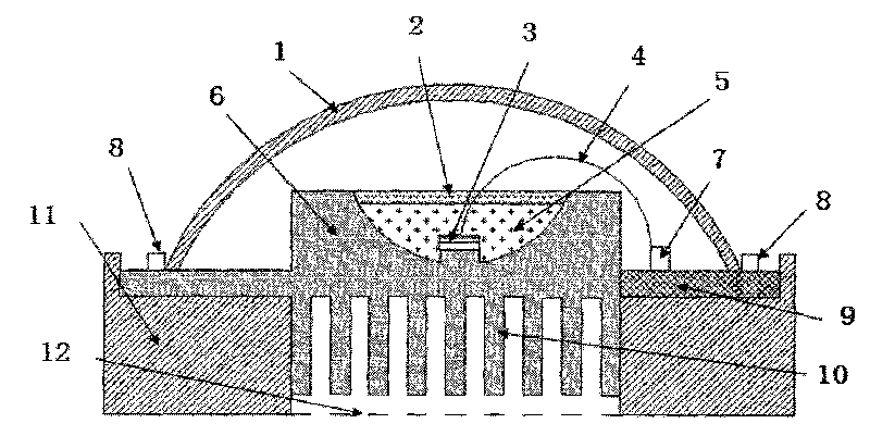
[0024] Example 1 as figure 1 As shown, the high-power LED heat dissipation packaging structure includes an aluminum heat sink 6 and a chip 3 arranged in the concave cavity of the aluminum heat sink 6. The anode of the LED chip 3 is connected to the internal terminal 7 through a gold wire 4, and the internal terminal 7 7 is connected to the external terminal 8 through the printed circuit board 9, and the lens 1 is potted on the aluminum heat sink 6 including the LED chip 3; wherein, the aluminum heat sink 6 has an inverted T-shaped structure and extends along its lower side There is a scaly heat sink 10 integrated with the aluminum heat sink 6, and a printed circuit board 9 is connected to the extension arm of the aluminum heat sink 6. The center of the aluminum heat sink 6 is provided with a hemispherical concave cavity, and the LED chip 3 Mounted on the boss on the bottom surface of the semi-spherical concave cavity in the center of the aluminum heat sink 6, the flexible sili...

Embodiment 2

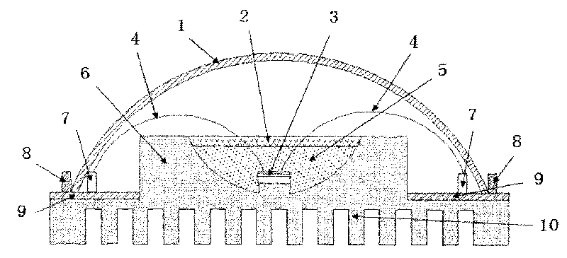
[0033] Example 2 as figure 2 As shown, the framework of this structure is substantially the same as that of Embodiment 1, except that a scale-shaped heat sink 10 integrally structured with the aluminum heat sink 6 extends below the inverted T-shaped aluminum heat sink 6 . There is no need to set up the plastic bracket 11 , the structure is simpler than that of Embodiment 1, and the link of the plastic bracket is omitted, and the fin-shaped structure at the bottom is conducive to the rapid dissipation of heat. Its heat dissipation effect is better than that of embodiment 1, but the difference is that its cost will be greater than that of embodiment 1.

[0034] The aluminum heat sink 6 of this structure is a double-arm structure, and the connection method of the upper end surfaces of the two arms is different from that of embodiment 1. The aluminum heat sink 6 of the double-arm structure and the scaly heat sink 10 of the integral structure of the aluminum heat sink 6 are vertic...


PUM


Abstract

The invention relates to a high-power LED packaging structure. The packaging structure is characterized in that an aluminum heat sink (6) is in the structure of an inverted T; a scalelike heat-dissipation plate (10) integrated with the aluminum heat sink (6) extends under the aluminum heat sink; an extending arm of the aluminum heat sink (6) is connected with a printed circuit board (9), the center of the aluminum heat sink (6) is provided with a semi-spherical surface concave cavity; a chip (3) is adhered to a lug boss on the inner bottom surface of the semi-spherical surface concave cavity; flexible silica gel (5) is packaged inside the semi-spherical surface concave cavity comprising the chip (3); and the top surface of the flexible silica gel (5) is coated with a fluorescent powder layer (2). The high-power LED packaging structure ensures that the heat of an LED can be dissipated quickly, thereby increasing the light-emitting stability and service life of high-power LEDs.

Description

technical field [0001] The invention relates to a package structure of a high-power LED, in particular to a package structure with uniform light emission and favorable heat dissipation of the high-power LED. Background technique [0002] LED (Light Emitting Diode) is a semiconductor light-emitting device. It is expected to become the next-generation lighting source due to its advantages such as high light efficiency, energy saving, high environmental protection and safety, long life, fast response, and low operating cost. In the context of increasingly scarce resources and deteriorating environment, energy-saving and environmentally friendly LED products have huge market prospects. [0003] At present, LED is widely used in landscape lighting, signal lights, automobile industry, backlight module, daily lighting and other fields, and its advantages are gradually emerging. However, with the wide application of LEDs, in the process of replacing other light sources, the market ...

Claims


Application Information

Patent Timeline
Patent Type & Authority Applications(China)
IPC IPC(8): F21V29/00F21V19/00F21V9/10H01L33/64H01L33/48F21Y101/02F21V9/40F21V29/503F21V29/70F21V29/76F21V29/89F21Y115/10
CPCH01L2224/48091H01L2224/73265
Inventor 赵金鑫
Owner IRICO
Why Eureka
Try Eureka