Full-automatic ball attachment machine

A fully automatic, ball-planting technology, applied in tin feeding devices, metal processing equipment, manufacturing tools, etc., can solve the problems of waste of solder paste, long processing time, and large consumption of solder paste, so as to reduce production costs and shorten the Processing time, the effect of improving production efficiency

Active Publication Date: 2010-04-28
CHONGQING QUNWIN ELECTRONICS MATERIAL CO LTD
View PDF0 Cites 5 Cited by
  • Summary
  • Abstract
  • Description
  • Claims
  • Application Information

AI Technical Summary

Problems solved by technology

Adopting above-mentioned procedure to carry out dispensing and planting ball on the substrate to be processed mainly has the following deficiencies: one, adopt to brush soldering paste on the template, only a part of soldering paste enters in the electric component installation hole on the substrate, causes another Part of the soldering paste is wasted, so the consumption of soldering paste is large and the production cost is high; 2. The solder balls are planted one by one by using a metal ball blanking device to align with the electrical component installation holes on the substrate to be processed. Not only the ball planting efficiency is low, but also the placement After placing a solder ball, the blanking tube needs to move a position, so there is a certain displacement deviation, which seriously affects the accuracy of the subsequent soldering position; 3. Because the dispensing is manually operated, the solder balls are placed one by one, so each The processing time of the station is long, which seriously affects the processing progress of the subsequent substrates, resulting in low production efficiency and high production costs for the substrates to be processed.

Method used


Image

  • Full-automatic ball attachment machine
  • Full-automatic ball attachment machine
  • Full-automatic ball attachment machine

Examples


Embodiment Construction

[0026] The present invention will be described in further detail below in conjunction with the accompanying drawings and specific embodiments.

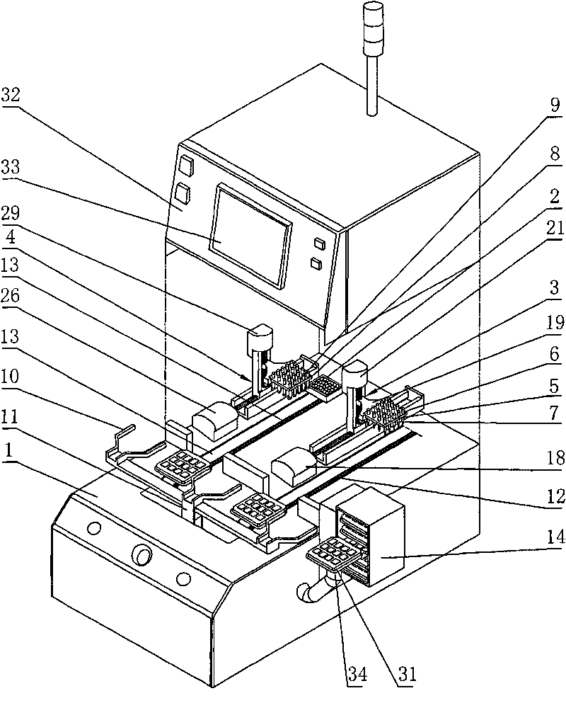
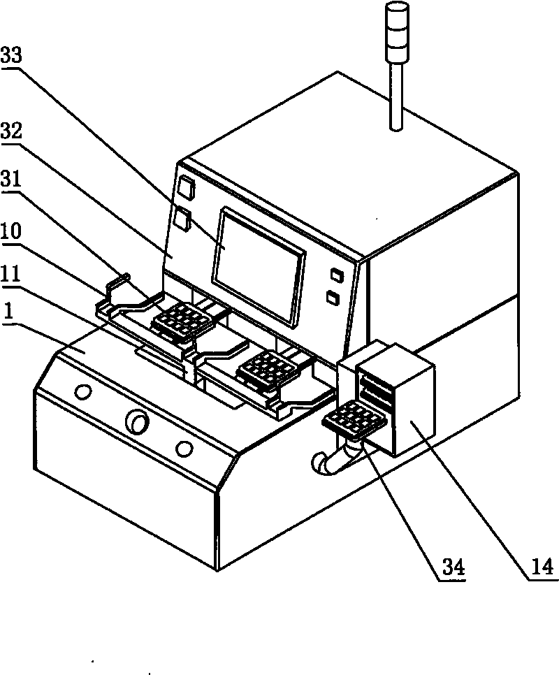
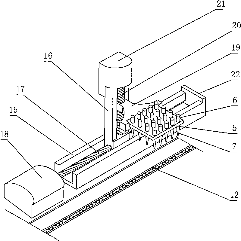
[0027] figure 1 It is the structural representation that the sealing cover of the present invention moves upwards to the workbench, figure 2 It is a schematic diagram of the appearance and structure of the present invention, as shown in the figure: the automatic ball planting machine includes a workbench 1, a conveyor chain arranged on the workbench 1, a solder ball storage disk 2, a loading and unloading manipulator 10, a substrate storage box 14, and The solder paste dripping device 3 is used to drip the solder paste into the electrical component installation holes on the substrate 31 to be processed, and the solder ball placement device 4 is used to place the solder balls in the electrical component installation holes on the substrate 31 to be processed. Conveyor chain comprises the dripping glue conveying chain 12 and the ball p...


PUM


Abstract

The invention discloses a full-automatic ball attachment machine, which comprises a workbench, a conveying chain arranged on the workbench, a solder ball storage disk, a flux paste dropwise-adding device which adds flux paste dropwise on substrates to be machined, and a solder ball placement device which places solder balls on the substrates to be machined. In the full-automatic ball attachment machine, the flux paste is directly injected into mounting holes of the substrates to be machined through a plurality of flux paste injection tubes on a dispensing mould, and the solder balls are placed into the mounting holes of the substrates to be machined through a plurality of vacuum ball absorption tubes on a ball attachment mould, so a plurality of substrates to be machined can be dispensed and placed once, positioning accuracy is high, raw materials are saved and production cost is reduced; and a whole power source is controlled by a PLC controller, thus the degree of automation is higher and operations are more convenient.

Description

technical field [0001] The invention relates to a welding processing equipment for a substrate to be processed, in particular to a fully automatic ball planting machine for dispensing glue into holes of a circuit substrate and planting balls. Background technique [0002] The substrate to be processed is mainly made by bonding the ball with solder paste, and welding the electrical components on the circuit board to be processed by melting the ball. Glue dispensing and ball planting are two important processes for processing the substrate to be processed, and the accuracy and efficiency of glue dispensing and ball planting will seriously affect the subsequent processing procedures. [0003] In the prior art, the dispensing process is to lay the prepared template on the substrate to be processed, so that the pre-designed holes on the template correspond to the electrical component installation holes on the processed substrate, and then brush a layer on the template. Soldering...

Claims


Application Information

Patent Timeline
Patent Type & Authority Applications(China)
IPC IPC(8): B23K3/06H05K3/34
Inventor 林文良
Owner CHONGQING QUNWIN ELECTRONICS MATERIAL CO LTD
Why Eureka
Try Eureka