Wide-flame close type fireplace

A closed, fireplace technology, applied in the direction of household stoves/stoves, lighting and heating equipment, solid heating fuels, etc., can solve the problems of low thermal efficiency, poor viewing effect, narrow flame, etc. Narrow, thermal effect

Inactive Publication Date: 2011-03-16
朱宏锋 +1
View PDF6 Cites 0 Cited by
  • Summary
  • Abstract
  • Description
  • Claims
  • Application Information

AI Technical Summary

Problems solved by technology

[0003] The purpose of the present invention is to provide a fireplace with large flame width, strong heat feeling, good viewing effect and high thermal efficiency to solve the problems of narrow flame, weak heat feeling, poor viewing effect and low thermal efficiency in the existing fireplace. Wide Flame Closed Fireplace

Method used


Image

  • Wide-flame close type fireplace
  • Wide-flame close type fireplace
  • Wide-flame close type fireplace

Examples


Embodiment 1

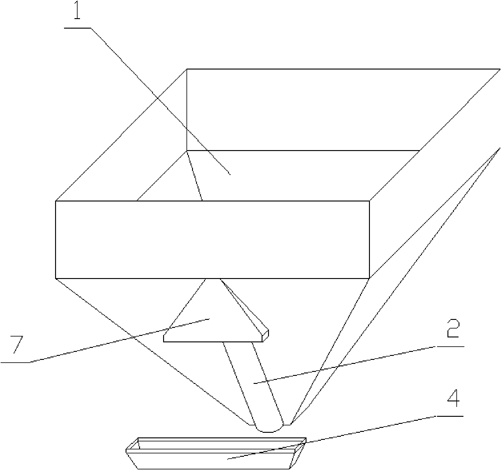
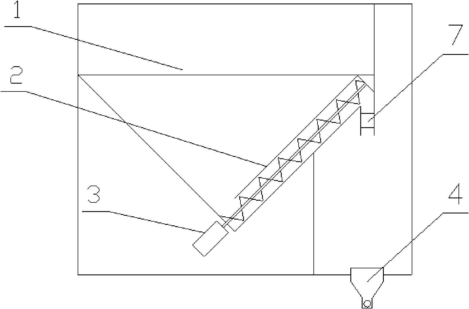
[0026] in such as figure 1 figure 2 In the shown embodiment 1, a wide flame closed fireplace includes a furnace, an air inlet and outlet system, and a hot air system. A ventilation duct and a combustion chamber (not shown in the figure) are arranged in the furnace, and a hopper is provided on the rear side of the furnace. 1 and the fuel conveying device 2, the front wall of the hopper 1 is the rear wall of the furnace, the fuel conveying device is an auger device driven by the motor 3, and is arranged on the bottom slope of the fireplace hopper, and the bottom of the combustion chamber is provided with a furnace box 4, The furnace box is a long groove structure, the bottom is provided with a heating rod 5, the two sides of the heating rod are provided with air inlets 6, the length of the furnace box is 60% of the width of the furnace, and the length direction of the furnace box is consistent with the width direction of the fireplace , the rear wall of the hearth above the fu...

Embodiment 2

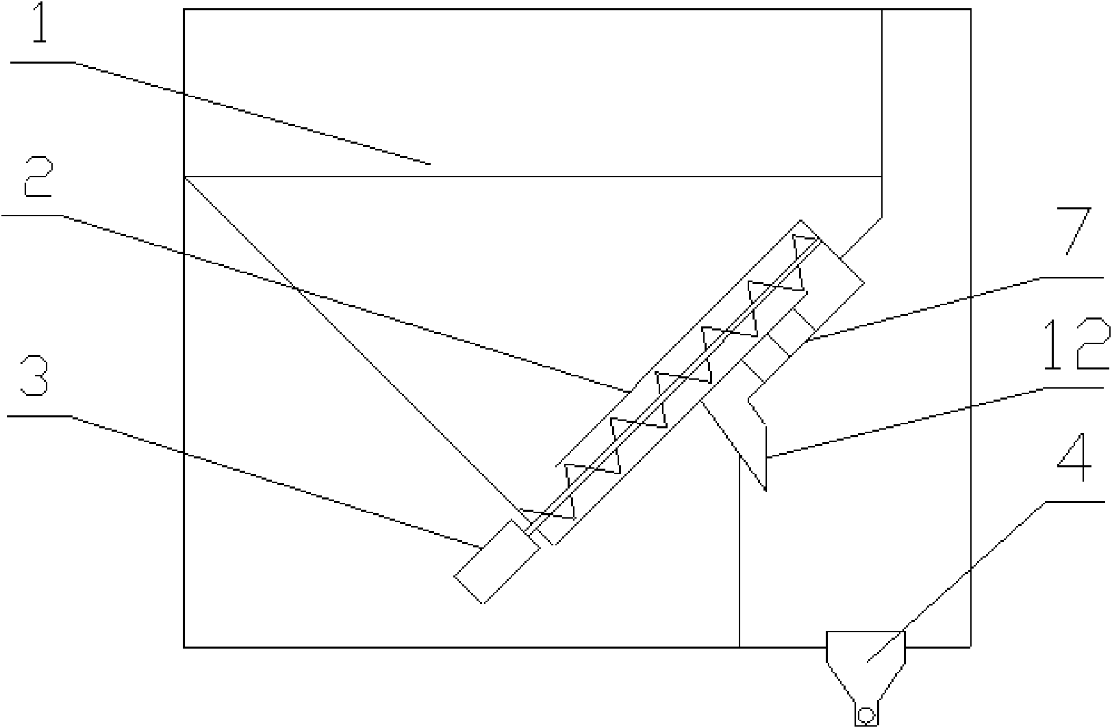
[0028] in such as image 3 In the shown embodiment 2, the length of the furnace box is 70% of the width of the furnace, the material distribution device is arranged obliquely, the feed inlet is arranged on the top side of the material distribution chamber, and the distribution rods in the material distribution chamber are arranged in layers and misplaced. , the distribution density of the distribution rods near the edges on both sides is greater than that of the distribution rods in the middle (see Figure 7 ), the material distribution chamber is close to the rear wall of the furnace, the discharge port of the material distribution device is connected with a guide device 12, and the outlet of the guide device is located at the side top of the furnace box, and the rest are the same as in embodiment 1.

Embodiment 3

[0030] in such as Figure 4 In the shown embodiment 3, the length of the furnace box is 50% of the width of the hearth, the distribution device is arranged obliquely, and is in a state perpendicular to the furnace wall, and the distribution cavity is an equal thickness structure, which is independently arranged (see Figure 8 ), the discharge port of the material distribution device is located above the side of the furnace box, the bottom of the furnace box is provided with a heating rod, the two sides of the heating rod are provided with air inlets, and the side wall of the furnace box near the rear wall of the furnace is provided with a number of air inlets hole 13 (see Figure 9 ), all the other are identical with embodiment 1.

[0031] The hearth, furnace door, air inlet and outlet system, hot air system and fuel delivery device of the wide-flame closed fireplace are basically consistent with the existing technology, and the working principle and working process of its co...


PUM


Abstract

The invention discloses a wide-flame close type fireplace, which comprises a hearth, a fuel conveying device and a hot air system, wherein a ventilation pipe and a combustion chamber are arranged in the hearth; the bottom of the combustion chamber is provided with a furnace box having a long-groove structure; the length direction of the furnace box and the width direction of the fireplace are consistent; a material distribution device is arranged on a hearth rear wall above the furnace box; the material distribution device comprises a material distribution chamber, a feed inlet and a discharge hole; the feed inlet connected with the fuel conveying device is arranged on the upper end of the material distribution chamber; the strip discharge hole is arranged on the lower end of the materialdistribution chamber; and the length direction of the discharge hole is consistent with the length direction of the furnace box. The wide-flame close type fireplace solves the problems of narrow flame, poor warm sense, poor aesthetic effect and low heat efficiency of the traditional fireplace and has wide flame, strong warm sense, excellent aesthetic effect, high heat efficiency, little harmful gas discharge and obvious economic and social benefits.

Description

technical field [0001] The invention relates to a fireplace, in particular to a wide-flame closed-type fireplace with large flame width, good viewing effect and high combustion efficiency. Background technique [0002] The main structure of the existing fireplace is composed of a combustion chamber and a base. The opening is set on the combustion chamber, facing the indoor side. The top of the combustion chamber is provided with a waste gas outlet. When in use, the fuel is manually fed into the combustion chamber through the opening. Indoors, the heat generated by combustion is transferred to the room through natural radiation, which makes the indoor temperature rise. The disadvantage of this kind of fireplace is that the thermal efficiency is low, and the heat generated by burning wood is transferred through radiation. The exhaust gas is discharged to the outside; the second is that the safety is poor. In the case of poor ventilation, it is easy to cause indoor hypoxia. Fo...

Claims


Application Information

Patent Timeline
Patent Type & Authority Patents(China)
IPC IPC(8): F24B1/18F24B1/191F24B1/19
Inventor 朱宏锋王竹宏
Owner 朱宏锋
Why Eureka
Try Eureka