
Method and Device for Laser Radiation Modulation

a laser radiation and modulation technology, applied in the field of laser technology, can solve the problems of destroying the plate or the ao crystal prism to which it is connected, high power density of the electric and acoustic fields at the piezotransducer, and destroying the plate or the ao crystal prism, etc., to achieve the effect of increasing the area of the piezotransducer, increasing the efficiency of ao interaction, and increasing the area of the piezo

Pending Publication Date: 2021-12-16
NATIONAL RESEARCH TECHNOLOGICAL UNIVERSITY
View PDF0 Cites 0 Cited by
  • Summary
  • Abstract
  • Description
  • Claims
  • Application Information

AI Technical Summary

Benefits of technology

The technical effect of this patent text is that by using the properties of a crystal's acoustic anisotropy, the area of the piezotransducer can be increased, which reduces the amount of high-frequency electric power needed and results in less intense heating. Additionally, the text describes a geometry for the acoustic interaction in a laser resonator Q-switch that allows for lower control high-frequency power and the ability to operate without additional efficiency loss with multimode or uncollimated laser radiation.

Problems solved by technology

A disadvantage of said prototype is a high power density of the electric and acoustic fields at the piezotransducer.
The high power density causes intense local heat release in the AO Q-switch piezotransducer.
Strong local heating of the piezoelectric plate may destroy the plate or the AO crystal prism to which it is connected because of the difference and anisotropy of the thermal expansion coefficients of the materials of the piezoelectric plate and the AO crystal.
A disadvantage of said prototype is a relatively low AO figure of merit M2 and hence high control HF power.
Another disadvantage of said prototype is a low diffraction efficiency when the device is operated with multimode or uncollimated lasers.
The hinder to the achievement of the required technical result for the prototype is that the Q-switch is operated with a quasi-longitudinal (QL) acoustic wave and the respective AO interaction geometry.

Method used


Image

  • Method and Device for Laser Radiation Modulation
  • Method and Device for Laser Radiation Modulation
  • Method and Device for Laser Radiation Modulation

Examples


Embodiment Construction

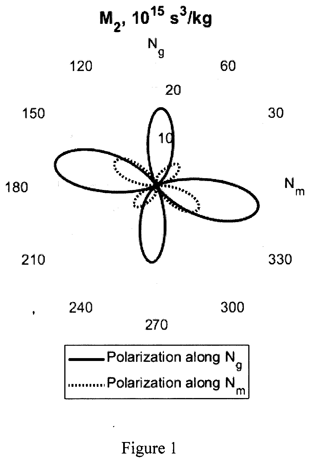
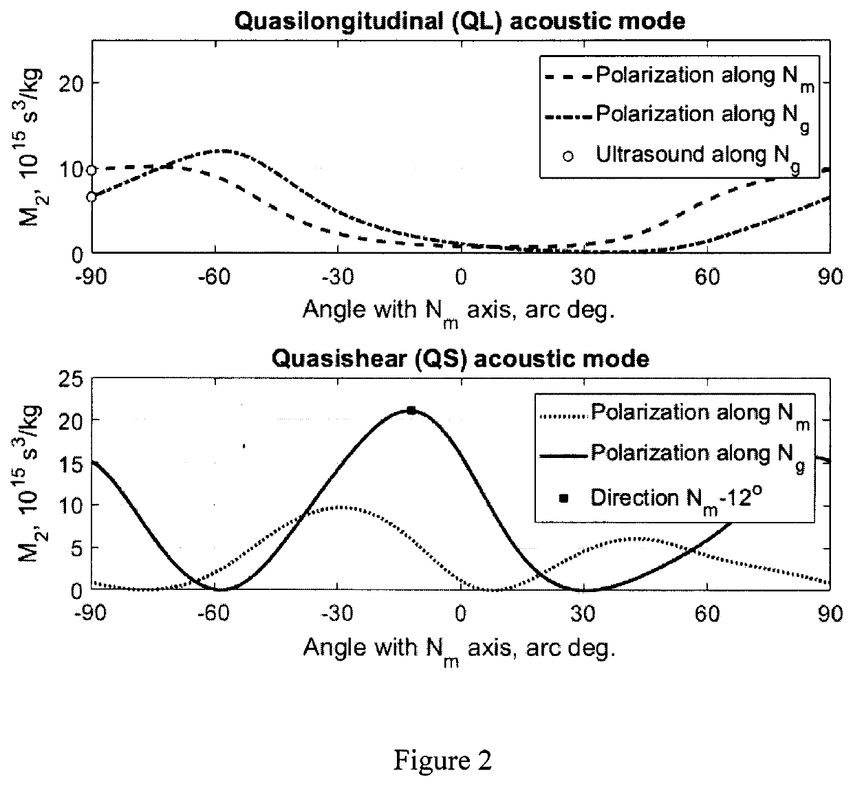
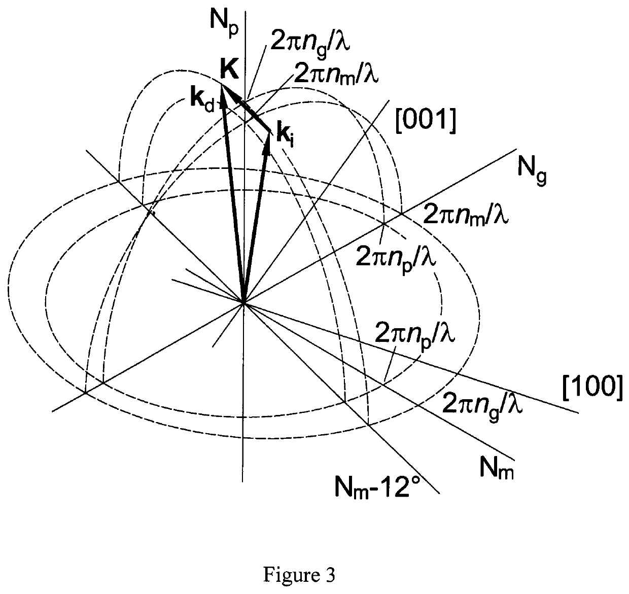
[0042]The present invention is implemented as follows. The acousto-optic Q-switch comprises an AO prism 1 made from a KRE(WO4)2 group single crystal and having an acoustic surface 2 which is parallel to the Np axis of the AO prism 1 crystal, its normal being at an angle of 0 to −30 arc deg relative to the Nm axis, an opposite surface 3, an input optical surface 4 which is orthogonal to the Np axis, an output optical surface 5 which is orthogonal to the Np axis, a piezotransducer 6 attached to said acoustic surface 2, and an acoustic absorber 7 attached to said opposite surface 3. Said piezotransducer 6 made from a lithium niobate plate with a thickness of 15 to 200 μm excites a quasi-shear acoustic wave 10 in said AO prism 1. Said acoustic absorber 7 is attached to the surface 6 of said AO prism 1 which is at an arbitrary angle to said acoustic surface 2 thus providing a traveling acoustic wave in said AO prism 1. The input laser beam 8 has the polarization 9 parallel to the Ng axis...


PUM


Abstract

The proposed method and device relate to acousto-optics and laser technology and can be attributed, in particular, to acousto-optical (AO) laser resonator Q-switches, AO devices for extra-cavity control of single-mode (collimated) and multimode (uncollimated) monochromatic and non-monochromatic laser radiation, i.e, AO modulators, AO frequency shifters, and dispersion delay lines for visible and middle IR wavelengths (0.4-5.5 μm). The object of the method and device is providing a geometry of AO interaction in laser resonator Q-switches so that to optimize the preset parameters of the Q-switch in accordance with the system requirements to the laser operation mode depending on the intended use of the laser, more specifically, lower control RF power and capability of operation without additional efficiency loss with multimode or uncollimated laser radiation.

Description

CROSS-REFERENCE TO RELATED APPLICATIONS[0001]This application is a U.S. national stage application of an international application PCT / RU2019 / 000663 filed on 23 Sep. 2019, whose disclosure is incorporated herein in its entirety by reference, which international application claims priority of a Russian Federation patent application RU2019106282 filed on 6 Mar. 2019.FIELD OF THE INVENTION[0002]The present invention relates to acousto-optics and laser technology and can be attributed, in particular, to acousto-optic (AO) laser resonator Q-switches, AO devices for extra-cavity control of single-mode (collimated) and multimode (uncollimated) monochromatic and nonmonochromatic laser radiation, i.e., AO modulators, AO frequency shifters, and dispersion delay lines from visible to middle infrared (IR) wavelengths (0.4-5.5 μm).BACKGROUND OF THE INVENTION[0003]AO interaction of light and ultrasound in crystals having high acoustic and photo-elastic anisotropy is considered to be one of the mo...

Claims


Application Information

Patent Timeline
IPC IPC(8): H01S3/117
CPCH01S3/117G02F1/011G02F1/11
Inventor MOLCHANOV, VLADIMIR YAKOVLEVICHYUSHKOV, KONSTANTIN BORISOVICHNAUMENKO, NATALYA FEDOROVNACHIZHIKOV, ALEXANDER ILICHGUROV, VASILY VIKTOROVICHPAVLYUK, ANATOLY ALEKSEEVICH
Owner NATIONAL RESEARCH TECHNOLOGICAL UNIVERSITY
Learn More