Method for manufacturing coil winding of magnetic conducting and electric conducting body

A technology of coil winding and manufacturing method, which is applied in coil manufacturing, inductance/transformer/magnet manufacturing, electric components and other directions, can solve the problems of small current generated by coil winding and excessive radial size, and achieves easy manufacturing and maintenance. Simple, easy-to-craft effects

Inactive Publication Date: 2010-04-28
刘刚
View PDF3 Cites 3 Cited by
  • Summary
  • Abstract
  • Description
  • Claims
  • Application Information

AI Technical Summary

Problems solved by technology

[0003] The present invention aims at the problems existing in the existing spiral-wound ring magnetic circuit closed generator, and provides a method for manufacturing the coil winding of the magnetic conductor, which effectively solves the problem that the radial dimension of the coil winding in this kind of generator is too large to cause the coil The technical defects such as small current generated in the winding can increase the current and power of the generator, so that the power of this kind of generator can reach the ideal performance

Method used


Image

  • Method for manufacturing coil winding of magnetic conducting and electric conducting body
  • Method for manufacturing coil winding of magnetic conducting and electric conducting body
  • Method for manufacturing coil winding of magnetic conducting and electric conducting body

Examples


Embodiment Construction

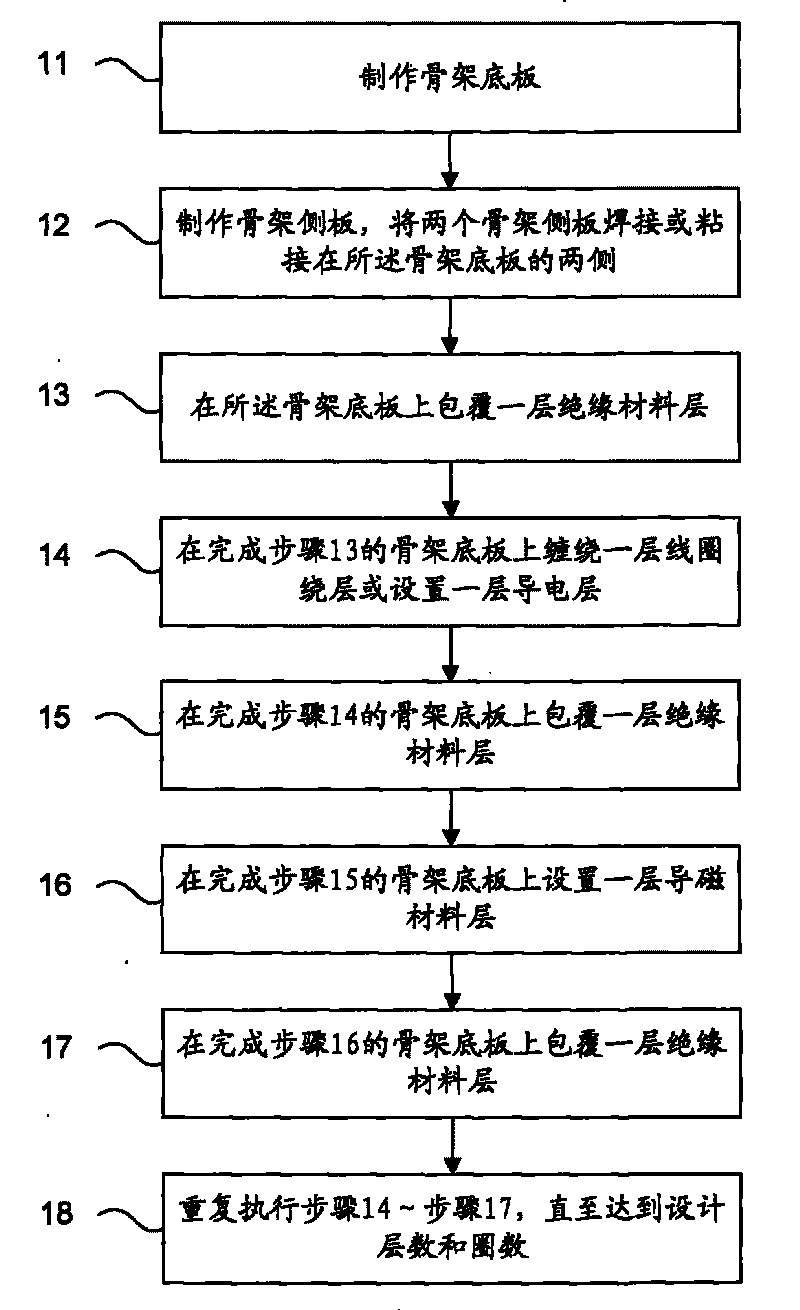
[0032] figure 1 It is a flow chart of the first embodiment of the manufacturing method of the magnetic conductor coil winding of the present invention, specifically including:

[0033] Step 11, making the skeleton bottom plate;

[0034] Step 12, making skeleton side plates, welding or bonding two skeleton side plates on both sides of the skeleton bottom plate;

[0035] Step 13, coating a layer of insulating material on the skeleton bottom plate;

[0036] Step 14, winding a layer of coil winding layer or setting a layer of conductive layer on the skeleton base plate after step 13;

[0037] Step 15, coating a layer of insulating material on the skeleton bottom plate after completing step 14;

[0038] Step 16, setting a layer of magnetically permeable material on the frame base plate after step 15;

[0039] Step 17, coating a layer of insulating material on the skeleton bottom plate after completing step 16;

[0040] Step 18. Repeat steps 14 to 17 until the number of layers ...


PUM

PropertyMeasurementUnit
thicknessaaaaaaaaaa
widthaaaaaaaaaa
lengthaaaaaaaaaa

Abstract

The invention discloses a method for manufacturing a coil winding of a magnetic conducting and electric conducting body, which comprises the following steps: manufacturing a framework bottom plate; manufacturing framework side plates, and welding or bonding the two framework side plates to the two sides of the framework bottom plate; wrapping an insulating material layer on the framework bottom plate; and arranging a magnetic conducting and electric conducting layer and the insulating material layer on the framework bottom plate completing the above steps in turn till reaching the designed layer number and number of turns. By arranging the magnetic conducting material layer between the coil winding layers, the method effectively solves the problems that the overlarge radial size of the coil winding in the prior art causes low current produced in the coil and the like, implements high current and high power of a generator, and achieves the ideal effect of the generator. The process of the method is simple; and the manufactured coil winding of the magnetic conducting and electric conducting body has a simple structure, is convenient for manufacturing and maintaining, can be used for electric equipment such as a magnetic closed generator, an electrical energy coupler, a transformer and the like, and has broad application prospect.

Description

technical field [0001] The invention relates to a method for processing and producing a magnetic induction coil, in particular to a method for manufacturing a coil winding of a magnetic conductor. Background technique [0002] As we all know, most of the coil windings in motors and generators are fixed on the stator, and the coils are insulated between the coils in the coil windings. In this way, when the hollow core part of the coil winding center is placed on the magnetic material, the coil windings are A current is generated after induction. Chinese patents 200520032106.6 and 200610094774.0 disclose a spiral-wound ring magnetic circuit closed generator. The coil winding is set on a magnetically conductive ring formed by a magnetically conductive material, and the side of the coil winding (that is, the radial peripheral surface) corresponds to the rotor magnet. Pole surface, so that the coil on the side of the coil winding is cut by the magnetic force lines of the magnet ...

Claims


Application Information

Patent Timeline
Patent Type & Authority Applications(China)
IPC IPC(8): H02K15/04H02K15/095H02K15/10H02K15/02H01F41/08H01F41/12H01F41/02
Inventor 刘刚
Owner 刘刚
Why Eureka
Try Eureka