Method suitable for low-speed switched reluctance motor without position sensor

A switched reluctance motor and sensor technology, which is applied in the direction of electronic commutator, electronic commutation motor control, electrical components, etc., can solve the problems of inflexible control, limited scope of application, etc., achieve simple implementation, improve accuracy, and algorithm simple effect

A switched reluctance motor and sensor technology, which is applied in the direction of electronic commutator, electronic commutation motor control, electrical components, etc., can solve the problems of inflexible control, limited scope of application, etc., achieve simple implementation, improve accuracy, and algorithm simple effect

CN101699757AInactive Publication Date: 2010-04-28NANJING UNIV OF AERONAUTICS & ASTRONAUTICS

Image

  • Method suitable for low-speed switched reluctance motor without position sensor
  • Method suitable for low-speed switched reluctance motor without position sensor
  • Method suitable for low-speed switched reluctance motor without position sensor

Examples


Embodiment Construction

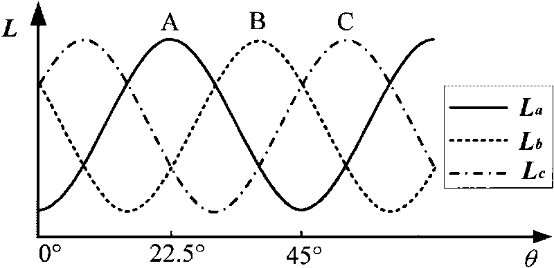
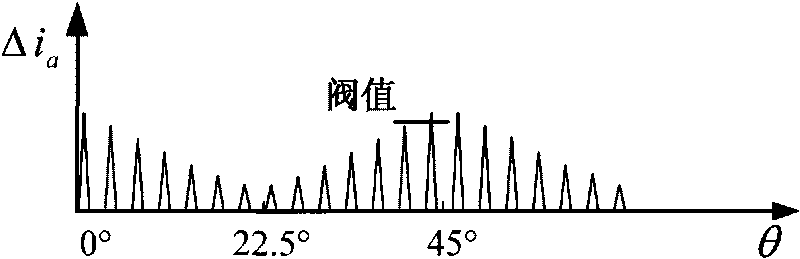
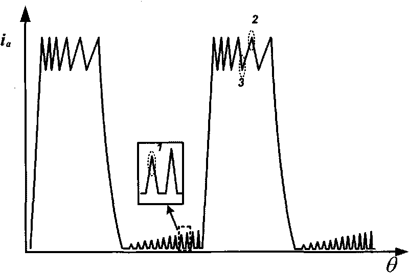
[0030] When the motor works in low-speed chopping mode, if high-frequency pulses are injected into the non-conducting phase, the switching tube will work in the state of being on and off continuously during the entire cycle. Low speed refers to the motor speed below 1500rpm. The high-frequency pulse frequency in the present invention is 10K--20KHz.

[0031] When the switch is turned on, the voltage equation can be expressed as formula (2):

[0032] v _ bus = Ri + L ( θ ) di dt | on + iw dL ( θ ) dθ - - - ( 2 )

[0033] When the switch is turned off, the voltage equation can be expressed as formula (3):

[0034] ...


PUM


Abstract

The invention discloses a method suitable for a low-speed switched reluctance motor without a position sensor, which belongs to the technical field of control of the switched reluctance motors. The method is as follows: taking the switched reluctance motor as a control object, injecting high frequency pulses into a non-conduction phase, detecting the differences between rising slopes and descending slopes of three-phase current during the whole period, filtering the discrete differences, and then forming three envelope lines respectively, thereby being capable of determining the position of a rotor according to cross points of the envelope lines due to the special relationship between the envelope lines and inductance, calculating other positions according to the rotational speed and further realizing the normal running of the motor and the adjustable control of a turn-on angle and a turn-off angle. The method has simple algorithm and flexible control, only the phase current needs to be detected, and the affects of counter potential are simultaneously eliminated, thereby improving the accuracy of position estimation to a greater extent.

Description

technical field [0001] The invention relates to a position sensorless method for switched reluctance motors suitable for low speed, and belongs to the technical field of position sensorless control of switched reluctance motors. Background technique [0002] Switched reluctance motor has the advantages of simple and firm structure, high efficiency, strong fault tolerance, flexible control, etc., and low price, so it has attracted much attention. Its application fields have involved aerospace, oil fields, electric vehicles, household appliances, etc. Gradually mature, has shown potential advantages and good prospects. [0003] The operation of the motor depends on the detection of the rotor position. Installing a position sensor not only increases the cost of the motor, but also reduces the reliability of the system in certain environments (due to the influence of high temperature and dust on the sensor). Therefore, the research of position sensorless technology is of great ...

Claims


Application Information

Patent Timeline
28 Apr 2010
Publication
CN101699757A
IPC
H02P6/18; H02P6/185
Inventors
毛宇阳; 邓智泉