Large flow jet servo valve driven by giant magnetostrictive actuator

A giant magnetostrictive and actuator technology, applied in servo motor components, fluid pressure actuation devices, mechanical equipment, etc., can solve the problems of low natural frequency of torque motor, limited response speed capability, large inertia of jet tube, etc. The effect of strong driving ability, large output force and high control precision

Inactive Publication Date: 2011-11-30
NANJING UNIV OF AERONAUTICS & ASTRONAUTICS
View PDF0 Cites 0 Cited by
  • Summary
  • Abstract
  • Description
  • Claims
  • Application Information

AI Technical Summary

Problems solved by technology

[0005] Whether it is the early ordinary jet tube servo valve or the later deflector plate type jet tube servo valve, its working reliability and work efficiency are much higher than that of the nozzle flapper servo valve, but its biggest disadvantage is the large inertia of the jet tube, which leads to the inherent torque motor part. The frequency is low, so the response is slow; the deflection plate jet tube servo valve has a greatly improved response speed due to the reduction of the inertia of the deflection part, but due to the limitation of the output power of the torque motor, the response speed is further improved and its ability to directly control the load is limited, and its control flow is also small

Method used


Image

  • Large flow jet servo valve driven by giant magnetostrictive actuator
  • Large flow jet servo valve driven by giant magnetostrictive actuator
  • Large flow jet servo valve driven by giant magnetostrictive actuator

Examples


Embodiment Construction

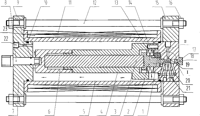
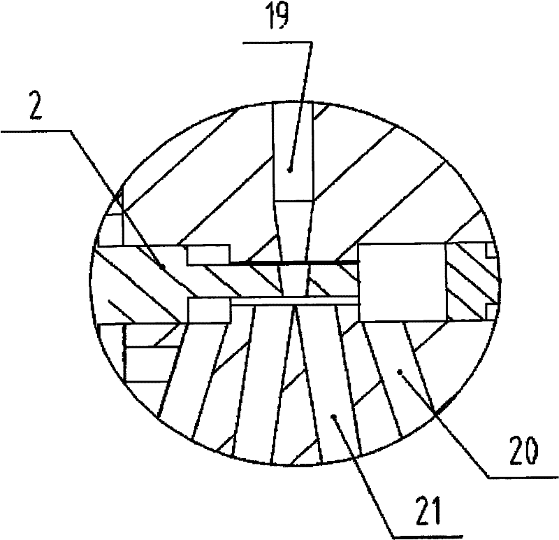
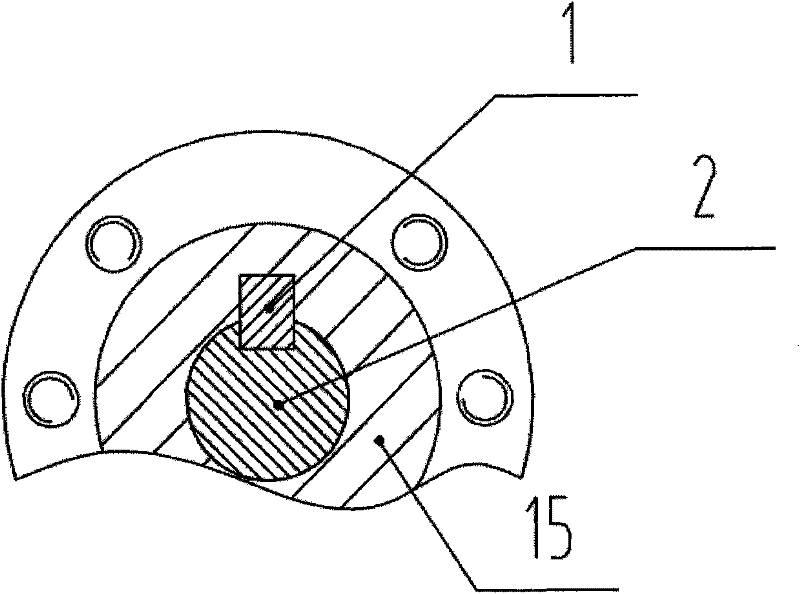
[0024] Such as figure 1, as shown in 2 and 3, the new jet servo valve includes a magnetic rod 8, a left end cover 7, a right end cover 15, a thermal compensation cover 4, and a thermal compensation slider 6, which are installed in the thermal compensation cover 4 and the thermal compensation slider 6 The giant magnetostrictive rod 3, the output slider 2, the preload spring 13, the coil bobbin 5 located outside the thermal compensation cover 4 and the thermal compensation slider 6, and the driving coil 23 and the bias coil wound around the coil bobbin 5 in turn Set the coil 11;

[0025] The new jet servo valve designs a new type of giant magnetostrictive actuator between the nozzle and the receiver of the traditional deflector type jet tube servo valve, and the actuator drives the output slider 2 to replace the original deflected jet tube servo valve torque motor and its Driven deflector, the new servo valve output slider 2 is directly driven by the giant magnetostrictive actu...


PUM


Abstract

The utility model relates to a high-frequency and large-flow jet servo valve driven by a giant magnetostrictive actuator, which belongs to the technical field of hydraulic servo control. Including the magnetic rod (8), the left end cover (7), the right end cover (15), the thermal compensation cover (4), the thermal compensation slider (6), installed on the thermal compensation cover (4) and the thermal compensation slider (6 ), the giant magnetostrictive rod (10), the output slider (2), the preload spring (13), the coil bobbin (5) outside the thermal compensation cover (4) and the thermal compensation slider (6), and It includes a drive coil (23) and a bias coil (11) which are sequentially wound outside the coil frame (5); the jet fluid servo valve has the remarkable characteristics of fast response, large drive power and control flow.

Description

technical field [0001] The invention relates to the application of giant magnetostrictive materials and belongs to the technical field of hydraulic servo control. Background technique [0002] The traditional structure of the jet tube servo valve is generally composed of torque motor, jet tube, nozzle, double receiver, etc. The torque motor is used to drive the deflection of the jet tube, and the deflection of the jet tube can change the pressure and flow in the double receiver. The flow change can be used to drive the slide valve or the hydraulic actuator in the small and medium power hydraulic servo system, and the control of the slide valve or the hydraulic actuator can be realized by controlling the output force and displacement of the torque motor. [0003] Due to the small output power of the torque motor, the early jet tube servo valves mostly adopted a two-stage structure, as described in Document 1 (Analysis and Design of Hydraulic Control Systems, edited by Lu Chan...

Claims


Application Information

Patent Timeline
Patent Type & Authority Patents(China)
IPC IPC(8): F15B13/02
Inventor 朱玉川王传礼李跃松鲍和云
Owner NANJING UNIV OF AERONAUTICS & ASTRONAUTICS
Why Eureka
Try Eureka