Method and device for determining commutation failure of high voltage direct current system

A technology of commutation failure and high-voltage direct current, which is applied in the field of power systems, can solve the problems of inapplicable commutation failure, inapplicable fault transient state, and inability to reflect the difference in fault transient process, so as to reduce the amount of calculation, reduce the amount of calculation, Effects that break through application limitations

Inactive Publication Date: 2010-05-05
SOUTH CHINA UNIV OF TECH
View PDF0 Cites 46 Cited by
  • Summary
  • Abstract
  • Description
  • Claims
  • Application Information

AI Technical Summary

Problems solved by technology

However, limited by the calculation scale and efficiency, the commutation failure discrimination method based on the measured electrical quantity is not suitable for the analysis of commutation failure in large-scale AC and DC systems, such as commutation failure risk assessment and optimal configuration of AC and DC system control and protection. Wait
Moreover, this discriminant method cannot study the internal mechanism of the influence of AC faults on commutation failures
The steady-state criteria for various commutation failures, such as the method based on the commutation voltage drop, are proposed from the perspective of fault steady-state, which cannot reflect the difference in the fault transient process corresponding to the difference in the fault closing angle. and the impact of this difference on commutation failure, so it cannot be applied to the study of fault transients

Method used


Image

  • Method and device for determining commutation failure of high voltage direct current system
  • Method and device for determining commutation failure of high voltage direct current system
  • Method and device for determining commutation failure of high voltage direct current system

Examples


Embodiment

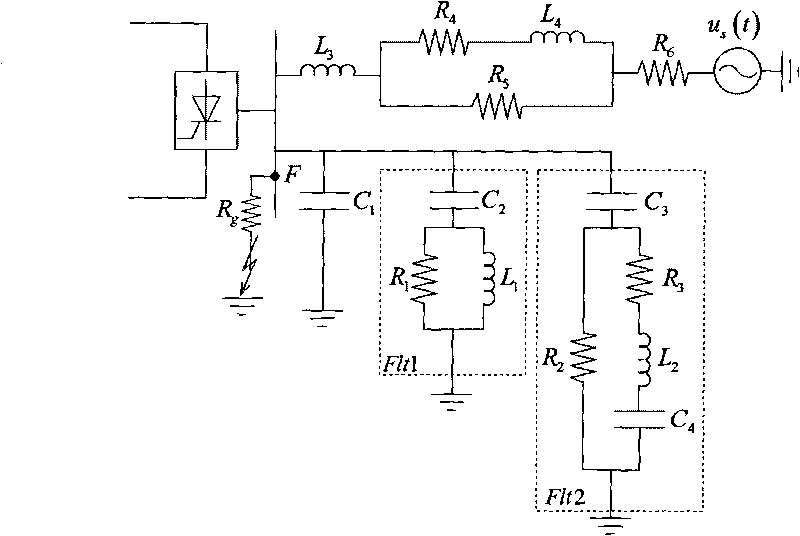
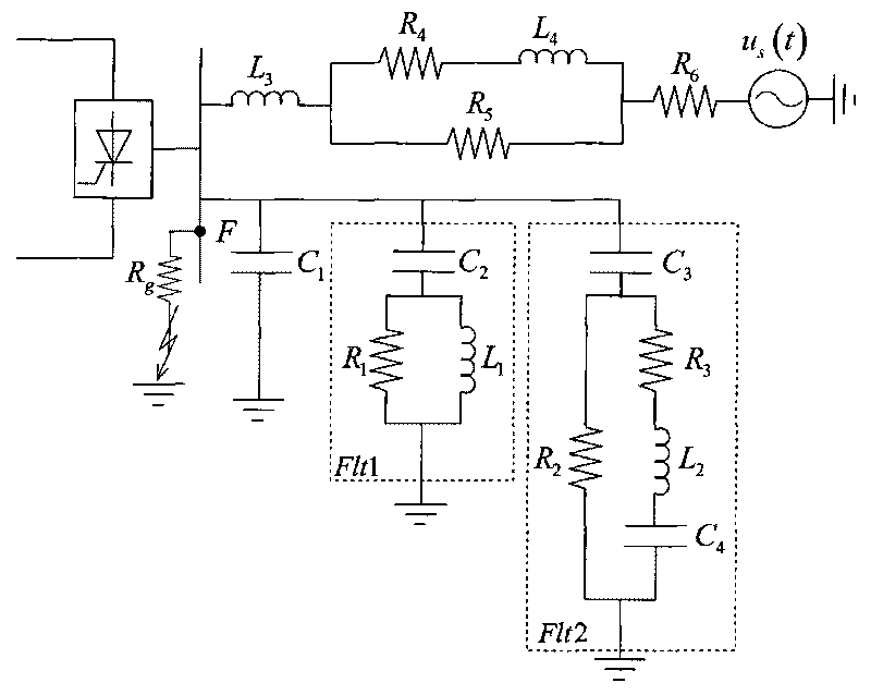
[0056] The structure of the AC system in the HVDC transmission system of the present invention is as follows figure 1 shown. Assume figure 1 A B-phase single-phase grounding fault occurs at middle F point, the transition resistance Rg=70 ohms, and the fault closing angle is 130°. Next, the device of the present invention is used to judge whether the failure of the AC system will cause the commutation failure of the HVDC power transmission system.

[0057] The device for judging commutation failure of the high-voltage direct current system includes:

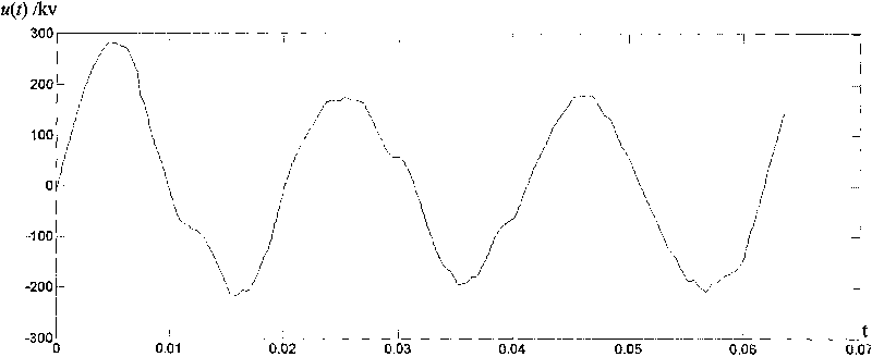
[0058] The preparation unit is used to calculate the load component and fault additional component of the commutation voltage on the commutation bus of the HVDC system when a specified fault occurs at a certain point in the AC system at a given fault closing angle, and obtain the commutation voltage time domain waveform;

[0059] A calculation unit is used to determine the integration interval according to the time domain wave...


PUM


Abstract

The invention discloses a method for determining the commutation failure of a high voltage direct current system, which comprises the following steps: S1 calculating the load component and the fault additional component of commutation voltage on a conversion bus of the high voltage direct current system when a fault occurs in a certain point thereof under a given fault close angle; S2 determining an integral interval and calculating the actual commutation voltage time area; S3 comparing the actual commutation voltage time area with the critical commutation voltage time area and determining whether the fault of the point can cause the commutation failure or not; S4 repeating the step S1 to step S3 and determining an alternating current fault region which causes the commutation failure of the high voltage direct current system. The invention further discloses a device for determining the commutation failure of the high voltage direct current system, which comprises a preparing unit, a calculation unit and a determining unit. The method and the device can greatly reduce the calculation scale, lead the precision to meet the needs of engineering applications, disclose the mechanism of how the fault close angle affects the commutation failure and be applicable to the analysis of fault steady state and fault transient state.

Description

technical field [0001] The invention relates to fault detection technology in the field of electric power systems, in particular to a method for judging phase commutation failure of a high-voltage direct current system caused by a fault in an alternating current and direct current hybrid system in an alternating current and direct current hybrid system, and a device using the method. Background technique [0002] With the implementation of the strategy of "West-East Power Transmission, North-South Mutual Supply, and National Networking" of my country's electric power industry, more and more high-voltage DC projects have been put into operation. At present, China Southern Power Grid has formed a "six AC and four DC" AC-DC hybrid transmission system, becoming the world's largest multi-infeed AC-DC hybrid system. In the AC-DC hybrid system, the commutation failure of the converter is one of the most common faults in the DC system. Continuous commutation failure not only seriou...

Claims


Application Information

Patent Timeline
Patent Type & Authority Applications(China)
IPC IPC(8): G01R31/08
Inventor 王钢李志铿黄敏李海锋朱革兰梁远升王智东
Owner SOUTH CHINA UNIV OF TECH
Why Eureka
Try Eureka