
Single-plunger double-displacement reciprocating rotation hydraulic drive

A hydraulic drive and reciprocating rotation technology, applied in the field of hydraulic pumps, can solve the problems of high material and processing accuracy, high oil cleanliness, inconvenient plug-in installation, etc., achieve low structural accuracy requirements, light weight, improve efficiency and The effect of longevity

Inactive Publication Date: 2017-05-24
黄增
View PDF4 Cites 0 Cited by
  • Summary
  • Abstract
  • Description
  • Claims
  • Application Information

AI Technical Summary

Problems solved by technology

[0003] The plunger pump has the following disadvantages: complex structure, high requirements for materials and processing accuracy, high price, and high requirements for oil cleanliness
The integration is poor. Each pump has an independent pump body, which is not convenient for plug-in installation. If a large flow output is required, only multi-pump combined pump group layout can be used; the noise and pulsation are relatively large

Method used


Image

  • Single-plunger double-displacement reciprocating rotation hydraulic drive
  • Single-plunger double-displacement reciprocating rotation hydraulic drive
  • Single-plunger double-displacement reciprocating rotation hydraulic drive

Examples


Embodiment Construction

[0025] The present invention will be further described below in conjunction with the accompanying drawings and embodiments.

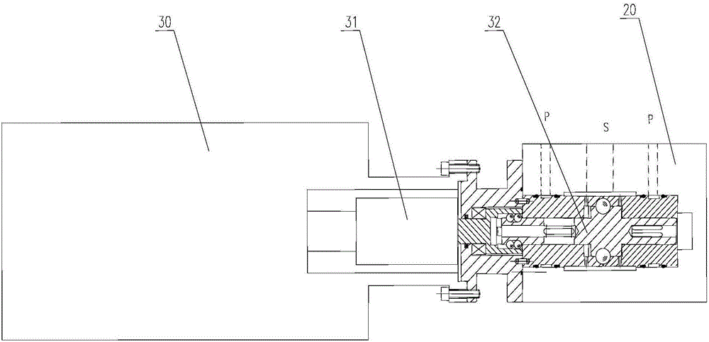
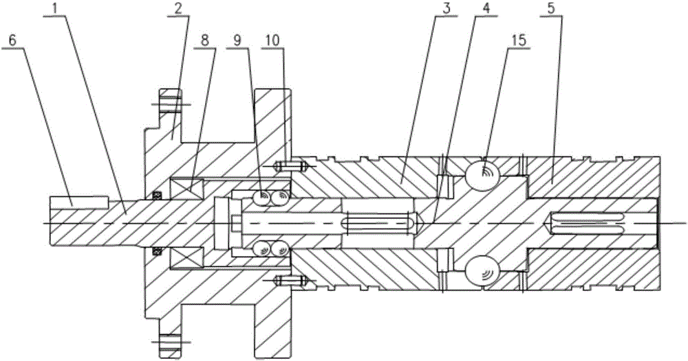
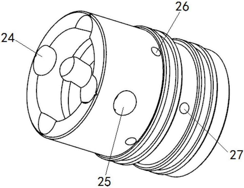
[0026] Such as Figure 1 to Figure 7 As shown, a single-plunger double-displacement reciprocating rotary hydraulic driver includes a motor 30, an input shaft 1, a front cover 2, a pump body 20, a pump sleeve, a pump core 4, a floating coupling, and high-precision steel balls 9 , Steel ball 15 etc.

[0027] The input shaft 1 is installed in the front end cover 2, and the pump sleeve is installed on the end surface of the front end cover 2. The pump sleeve has an oil suction port S and two oil discharge ports P. The pump sleeve is equipped with a pump core 4. One end of the input shaft 1 is connected to the motor, and the other end is The pump core 4 is connected by a floating coupling, and the motor 30 drives the pump core 4 to rotate in the pump sleeve through the input shaft 1. The pump sleeve and the pump core 4 pass through the semicircular groove 2...


PUM


Abstract

The invention relates to a single-plunger double-displacement reciprocating rotation hydraulic drive. The single-plunger double-displacement reciprocating rotation hydraulic drive is provided with an input shaft mounted in a front end cover, and a pump sleeve on the end surface; the pump sleeve is provided with an oil sucking port and two oil discharge ports; one end of the input shaft is connected with a motor, and the other end of the input shaft is connected with a pump element through a float coupling; the pump sleeve and the pump element are connected through matching a semicircular groove in the cylinder surface of the pump element with a steel ball in the spherical surface of the pump sleeve, so that the pump element performs an axial reciprocating motion along the groove in the cylinder surface of the pump element during rotating; blind holes and oil grooves are respectively formed in the centers of two ends of the pump element, wherein the blind hole at one end and the input shaft form a left end closed oil cavity of the pump, and the blind hole at the other end, the pump sleeve and a pump body form a right end closed oil cavity of the pump; the pump element rotates; the oil grooves of the pump element are alternately switched and communicate with the oil sucking port and the oil discharge ports of the pump sleeve; meanwhile, the sizes of the left and right two closed oil cavities are alternately changed along with left-right axial reciprocating motion of the pump element; the oil suction and discharge are realized; and the double-displacement output is formed. A working medium is such fluids as hydraulic oil or a water medium.

Description

technical field [0001] The invention relates to a hydraulic pump, in particular to a reciprocating rotary hydraulic driver, the working medium is fluid such as hydraulic oil or water medium. Background technique [0002] The plunger pump has the advantages of high rated pressure, compact structure, high efficiency and convenient flow adjustment, and is widely used in high pressure, large flow and flow adjustment occasions, such as hydraulic presses, engineering machinery and ships. Piston pumps are divided into two representative structural forms: axial piston pumps and radial piston pumps. It relies on the reciprocating movement of the plunger in the cylinder to change the volume of the sealed working chamber to realize oil absorption and oil pressure. Due to its complex structure and large volume, radial piston pumps have been replaced by axial piston pumps in many occasions. The axial piston pump works by using the volume change caused by the reciprocating movement of t...

Claims


Application Information

Patent Timeline
Patent Type & Authority Applications(China)
IPC IPC(8): F04B17/03F04B53/16F04B53/00
CPCF04B17/03F04B53/00F04B53/16
Inventor 黄增
Owner 黄增
Learn More