Detection circuit for partial discharge of capacitor

A partial discharge detection and capacitor technology, applied in the field of detection, can solve the problems of large quantitative error, inability to accurately measure capacitor discharge value, and decreased detection sensitivity.

Active Publication Date: 2010-05-05
NANTONG KAILAITE MACHINERY
View PDF0 Cites 9 Cited by
  • Summary
  • Abstract
  • Description
  • Claims
  • Application Information

AI Technical Summary

Problems solved by technology

At present, there are two main methods for detecting the internal discharge of high-voltage power capacitors, one is the ultrasonic detection method, and the other is the pulse current method. The disadvantage of using the ultrasonic detection method is that the quantitative error is large, and sometimes it cannot accurately measure the internal discharge of the capacitor. The discharge value of the discharge value; the pulse current method is to connect the capacitor of the test product in series with the primary coil of the coupling transformer and then connect it to the AC test power supply for the test, and judge the internal discharge of the capacitor under test by detecting the pulse current signal in the secondary coil of the transformer
The disadvantage of this method is that the leakage current of the capacitor is very weak relative to the test current flowing through it, and it is not easy to detect, and when the test current in the series circuit is large, it will saturate the coupling transformer, resulting in detection Decreased sensitivity, or even undetectable

Method used


Image

  • Detection circuit for partial discharge of capacitor
  • Detection circuit for partial discharge of capacitor
  • Detection circuit for partial discharge of capacitor

Examples


Embodiment Construction

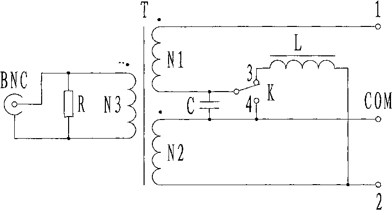
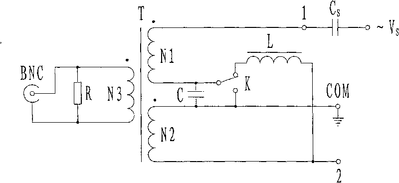
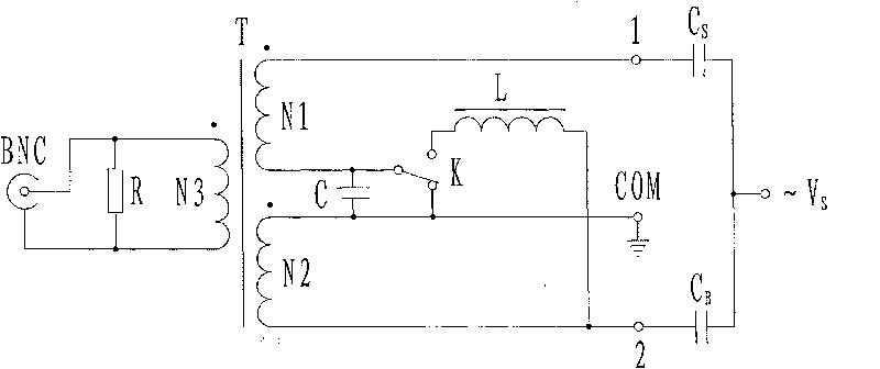
[0015] see figure 2 , in the unbalanced test mode, the unbalanced contact 3 of the test mode switch K is closed, the balanced contact 4 is opened, and the unbalanced input terminal 1 is connected to the capacitor C of the test object S , the balanced input terminal 2 is not connected to the standard capacitor C B , so the test is more convenient. After the test power is turned on, since the inductance L is in a short-circuit state for low-frequency signals and high-impedance for high-frequency signals, while the capacitor C is in a high-impedance state for low-frequency signals and short-circuit for high-frequency signals, the low-frequency test current signal is from The head end of N1 enters and flows out from the end of N1. After passing through the inductor L, it enters from the end of winding N2 and flows out from the head end of N2. The magnetic fields generated in the two windings are completely opposite and cancel each other out; the high-frequency discharge pulse si...


PUM


Abstract

The invention relates to a detection circuit for the partial discharge of a capacitor, which is used for detecting the partial discharge signals of a high-voltage capacitor. The detection circuit comprises a self-balancing coupling transformer, an inducer and a capacitor, wherein the self-balancing coupling transformer comprises an iron core and three coils, and the first coil has the same structure as that of the second coil. The head end of the first coil is an unbalanced input end connected with a test power supply through a sampling capacitor, and the tail end of the first coil is connected with the tail end of the second coil through the inducer and connected with the head end of the second coil through the capacitor. The head end of the second coil is connected with a signal public end, and partial discharge signals outputted from the two ends of the third coil are connected with a partial discharge tester. The invention can work at two test modes: unbalanced mode and balanced mode, and can separate out partial discharge pulse current signals when an impedance magnetic core is approximate to zero magnetic flux at either test mode. The self-balancing coupling transformer can not be saturated, therefore the sensitivity of partial discharge detection can not be influenced by the current size in a main loop.

Description

technical field [0001] The invention relates to a circuit for detecting a partial discharge signal of a high-voltage power capacitor, which belongs to the technical field of detection. Background technique [0002] In the production process of high-voltage power capacitors, it is necessary to test their insulation performance by detecting the amount of discharge inside them. At present, there are two main methods for detecting the internal discharge of high-voltage power capacitors, one is the ultrasonic detection method, and the other is the pulse current method. The disadvantage of using the ultrasonic detection method is that the quantitative error is large, and sometimes it cannot accurately measure the internal discharge of the capacitor. The discharge value of the discharge value; the pulse current method is to connect the capacitor of the test product in series with the primary coil of the coupling transformer and then connect it to the AC test power supply for the te...

Claims


Application Information

Patent Timeline
Patent Type & Authority Applications(China)
IPC IPC(8): G01R31/14
Inventor 何平高生刘大永景崇友赵秀生
Owner NANTONG KAILAITE MACHINERY
Why Eureka
Try Eureka