Bus wireless stop announcing system and method

A technology for buses and bus stops, applied in traffic control systems, traffic control systems for road vehicles, wireless communications, etc., can solve problems such as inability to correctly distinguish uplinks and downlinks, inability to receive data, and missed reports by buses , to achieve the effect of ensuring efficient and fast operation, improving the waiting environment, and facilitating waiting

Inactive Publication Date: 2010-05-05
毛建鑫
View PDF0 Cites 16 Cited by
  • Summary
  • Abstract
  • Description
  • Claims
  • Application Information

AI Technical Summary

Problems solved by technology

[0004] After the analysis of the above principles, the bus station reporting system based on GPS positioning has the following problems: GPS positioning accuracy is limited. In actual use, if GPS is affected by bridges and high-rise buildings, it is easy to fail to receive data, which will cause bus Missing vehicle reporting; the distance between the bus stops on the uplink and downlink lines is very short. When the accuracy of the GPS is within 100m, the system will not be able to correctly distinguish the uplink and downlink lines, especially when the vehicle enters the station quickly, and the vehicle moves every second. The distance plus the error distance, this problem is more prominent
However, its application to the public transport system itself has certain limitations, because ZigBee is a short-distance, low-speed wireless network technology, and it has an advantage in data transmission in small areas, but it cannot be used in large areas such as urban bus systems. Failure to meet technical requirements
Especially when there are multiple vehicles passing by a platform, the amount of data to be transmitted by the system will increase greatly, which will cause problems in the data transmission of the nodes of the system, resulting in a significant decline in system stability and reliability, which makes the system in the actual environment Limited in processing power
The same system also has the problems of poor flexibility and portability

Method used


Image

  • Bus wireless stop announcing system and method
  • Bus wireless stop announcing system and method
  • Bus wireless stop announcing system and method

Examples


Embodiment Construction

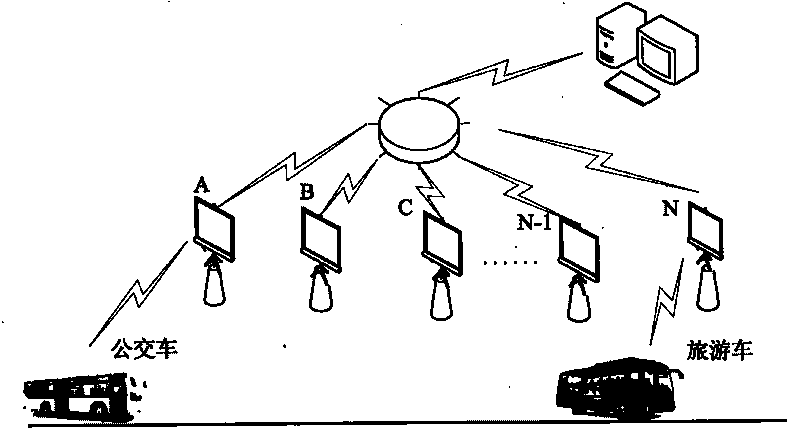
[0045] figure 1 A schematic diagram of the functions of the new bus stop reporting system, such as figure 1 As shown, Embodiment 1 of the novel bus station reporting system includes bus user terminals, other user terminals, bus station A, bus station B, bus station C, bus station N-1, and bus station N , bus metropolitan area network, management terminal. The bus user is about to drive into platform A. When the short-distance wireless module reaches the operating distance, the bus sends a request signal. At this time, platform A establishes communication with the bus that sent the request after receiving the request signal, and the platform records the bus user data at the same time. and location information, and transmit the voice coding data stream and Chinese character display code stored in the platform to the bus. After the bus is received, it will play the voice of the station name, and the LED will display the name of the upcoming station. Bus users The terminal and t...


PUM


Abstract

The invention relates to a bus and a bus stop automated management system, in particular to bus wireless stop announcing system and method. The bus wireless stop announcing system comprises a management terminal, at least one bus stop terminal and at least one user terminal, wherein the management terminal is connected with all bus stop terminals by a wired or wireless network so as to transmit information in two directions; and the bus stop terminals are connected with the user terminals in a wireless way so as to transmit the information in the two directions. The stop announcing system can finish a voice and Chinese character display prompt of a name of a stop to be arrived, which is preannounced by a bus without artificial operation in the whole process; meanwhile, the bus stop finishes the prompt of the information of vehicles being about to arrive at the stop and the information of the positions in which all the vehicles are located on a line, thereby bringing convenience to passengers.

Description

technical field [0001] The invention relates to an automatic management system for buses and bus stops, in particular to a wireless bus station announcement system and a station announcement method. Background technique [0002] The urban public transportation system is an important symbol of the image of urban civilization. With the development of science and technology, the urban public transportation system is about to enter a new era. In the past, the traditional bus station announcement system was the bus manual button station announcement and artificial voice station announcement. Due to the time-consuming and labor-intensive, high rate of misreporting and misreporting, and the hidden dangers of traffic safety, they will gradually withdraw from the historical stage, and under the background of the new era. The public transportation system puts forward new requirements, and the automation, intelligence, multi-purpose, economical, efficient management and visual manageme...

Claims


Application Information

Patent Timeline
Patent Type & Authority Applications(China)
IPC IPC(8): G08G1/123G08G1/133H04W4/00
Inventor 毛建鑫
Owner 毛建鑫
Why Eureka
Try Eureka