Post-pouring functional zone combined track beam

A technology of functional areas and track beams, applied in the field of track beams, can solve problems such as increased noise, poor finish, and difficult construction, and achieve the effects of reducing load-bearing capacity requirements, changing noise directivity, and facilitating processing and transportation

Inactive Publication Date: 2010-05-12
TONGJI UNIV
View PDF0 Cites 3 Cited by
  • Summary
  • Abstract
  • Description
  • Claims
  • Application Information

AI Technical Summary

Problems solved by technology

[0004] 1. Due to the complex shape of the prestressed concrete beam section, especially the structure of the oblique web and the support corbel, it brings certain difficulties to formwork production, steel bar binding and concrete pouring
Concrete surface is prone to pitting and poor finish
[0005] 2. The functional parts are only connected to the connectors pre-buried on the concrete beams by bolts, and the functional parts are not connected to each other. The stiffness of the functional parts cannot be fully utilized, resulting in a large structure and difficulties in processing and transportation
[0006] 3. There are gaps between functional parts and concrete beams, and between functional parts and functional parts, which increase the noise when the train runs at high speed
[0007] 4. The connecting parts are integrally poured in the prestressed concrete beam. In order to ensure that the connecting parts have a certain cutting allowance during machining, the connecting parts require high positioning accuracy requirements during pre-embedding construction, and the construction is difficult. Once the connecting parts If failure occurs during pre-embedding, machining or operation, it will affect the use function of the entire beam, and the design method is not reasonable enough

Method used


Image

  • Post-pouring functional zone combined track beam
  • Post-pouring functional zone combined track beam
  • Post-pouring functional zone combined track beam

Examples


Embodiment Construction

[0023] Embodiments of the present invention will be further described below in conjunction with the accompanying drawings.

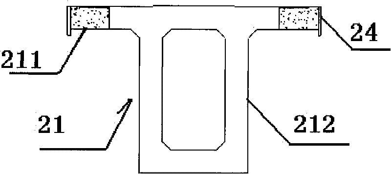
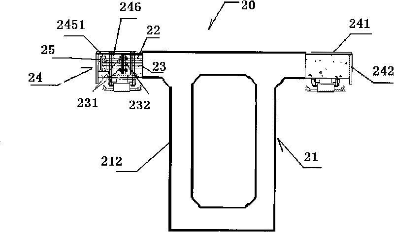
[0024] For the specific implementation of the post-cast functional area combined with the track beam 20 of the present invention, please refer to figure 2 and image 3 As shown, the support beam 21 is composed of post-cast functional areas 211 on both sides of the upper flange and an upright web 212 vertically arranged at the bottom of the support beam 21; The connecting piece 23; the two sides of the support beam 21 are respectively provided with steel functional parts 24; the transverse insertion bars 22 are inserted into the steel functional parts 24; the support beam 21 and the steel functional parts 24 are connected by bolts.

[0025] The first part is the prestressed concrete support beam 21, and the transverse ribs 22 protrude from the cantilever on both sides of the upper flange. It is vertically arranged at the lower part of the support beam ...


PUM


Abstract

The invention relates to a post-pouring functional zone combined track beam, comprising a support beam and steel functional components. The lower part of the support beam is provided with a webplate, and two sides of the upper wing edge of the webplate are provided with post-pouring functional zones; a transverse dowel bar and a connecting piece respectively extend out of cantalevers at two sides of the upper wing edge of the support beam extend; two sides of the support beam are respectively provided with the steel functional components; the transverse dowel bar is inserted into the steel functional components; the connecting piece of the support beam is firstly connected with the steel functional components, and then concrete is poured and filled among the steel functional components and in the steel functional components, and a post-pouring functional zone is formed after solidification. In the invention, the functional zones finally become an integer, thereby the purpose of rigidity utilization is realized, the weight of the beam is reduced, and the difficulty for transportation is reduced. Simultaneously, a gap does not exist in the longitudinal direction and the transverse direction of the track beam after formation so that the function of reducing operation noise is also achieved.

Description

technical field [0001] The invention relates to a track beam in a maglev transportation system, in particular to a post-casting functional zone combined track beam. Background technique [0002] At present, the track beam structure adopted by the maglev Shanghai demonstration line is a composite beam, please refer to figure 1 As shown, the composite track beam 10 in the prior art is composed of a support beam 12 and steel functional components 14 arranged on both sides of the support beam 12 , and a diagonal web 11 is provided at the lower part of the support beam 12 . That is to say, the functional area is a prefabricated integral steel functional part, which is composed of a sliding plate, a guide plate, a stator wing plate, a functional part web, and a partition. The pre-embedded connectors 13 in the concrete beams are machined and connected to the functional parts by bolts. According to the precise coordinate positioning of the connectors machined, the curved surface re...

Claims


Application Information

Patent Timeline
Patent Type & Authority Applications(China)
IPC IPC(8): E01B25/30E01B25/32
Inventor 吴祥明房庆强周质炎万建军颜克明窦仲赟叶丰陈定祥成广伟李文沛曾国锋
Owner TONGJI UNIV
Why Eureka
Try Eureka