
Method and device for controlling induced draft temperature of grate cooler of cement afterheat generation system

A technology of waste heat power generation and grate cooler, which is applied in the direction of temperature control, temperature control, non-electric variable control, etc. by using electric mode, and can solve the problems of temperature fluctuation of the waste heat of the cooler, which is not conducive to system operation, etc.

Inactive Publication Date: 2010-05-12
SOUTH CHINA UNIV OF TECH +1
View PDF0 Cites 7 Cited by
  • Summary
  • Abstract
  • Description
  • Claims
  • Application Information

AI Technical Summary

Problems solved by technology

The waste heat of the grate cooler utilizes large fluctuations in the exhaust temperature, which is not conducive to the stable and efficient operation of the system

Method used

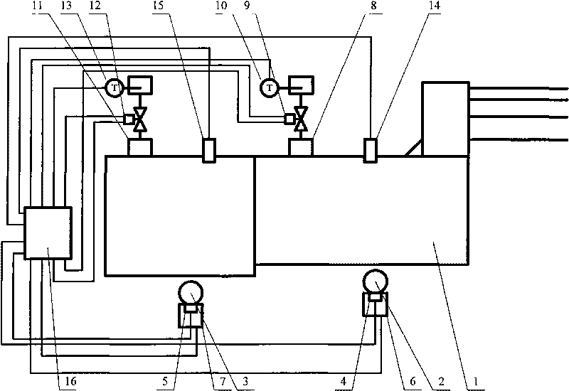
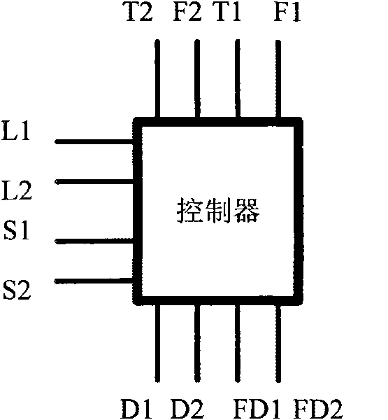
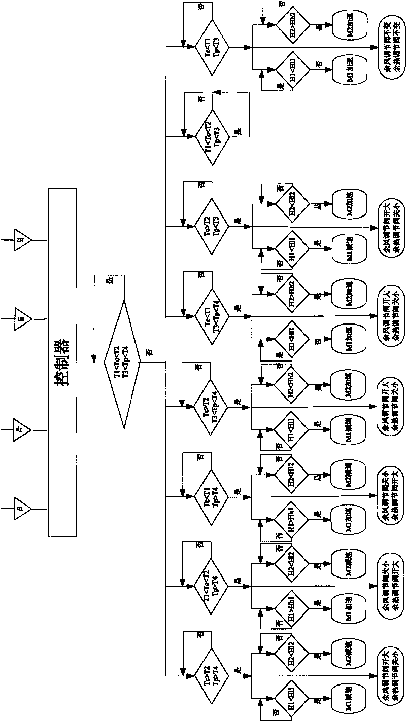

Image

  • Method and device for controlling induced draft temperature of grate cooler of cement afterheat generation system
  • Method and device for controlling induced draft temperature of grate cooler of cement afterheat generation system
  • Method and device for controlling induced draft temperature of grate cooler of cement afterheat generation system

Examples


Embodiment 1

[0044] This embodiment is a grate cooler exhaust temperature control method used in a cement waste heat power generation system. The controller realizes the opening of the waste heat utilization damper in the grate cooler, the opening of the residual air damper, and the rotational speed of a section of the main transmission shaft. and the speed of the second-stage main transmission shaft are controlled, such as Figure 4 As shown, it specifically includes the following steps:

[0045] (1) In the controller 16, the set value ranges of waste heat utilization exhaust temperature, residual air temperature, the first stage material level of the grate cooler and the second stage material level of the grate cooler are respectively set;

[0046] (2) Waste heat utilizes the exhaust air temperature detector 10 and the residual air temperature detector 13 to detect the real-time wind temperature in the waste heat exhaust pipe 8 and the waste air exhaust pipe 11 respectively, and the obta...

Embodiment 2

[0075] This embodiment is used in the grate cooler exhaust temperature control method and device of the cement waste heat power generation system. Compared with the first embodiment, the difference lies in the analysis and calculation of the data by the signal analysis and processing unit of the controller in the control method Adopt fuzzy control.

[0076] Fuzzy control divides the input parameters and output parameters into several levels, and then summarizes the fuzzy correspondence between input and output according to theoretical analysis and experimental experience, and formulates control rules. In this embodiment, the method for analyzing and calculating using fuzzy control is as follows:

[0077] (1) Set fuzzy variables

[0078] a. Waste heat utilization exhaust temperature (YCW): basic domain [250°C, 450°C], quantitative grade range [-5, +5]. Preset fuzzy subset: {too high, slightly high, normal, slightly low, too low}, abbreviated as: {TH, SH, OK, SL, TL};

[0079...


PUM


Abstract

The invention provides a method and a device for controlling an induced draft temperature of a grate cooler of a cement afterheat generation system. The method comprises the step of controlling afterheat using air valve opening, the afterwind valve opening, a rotating speed of a first main transmission shaft and a rotating speed of a second main transmission shaft in the grate cooler by using a controller. The device comprises the grate cooler, a first drive mechanism and a second drive mechanism which are connected with the grate cooler, an afterheat using mechanism and an afterwind emission mechanism, wherein the grate cooler, the afterheat using mechanism and the afterwind emission mechanism are arranged on the grate cooler. The grate cooler is provided with at least two stock level detectors; the first drive mechanism, the second drive mechanism, the afterheat using mechanism, the afterwind emission mechanism and the stock level detectors detector are respectively connected with the controller; and the controller is provided with a signal input end, a signal analysis processing unit and a signal output end, which are sequentially connected. The control device can effectively reduce the fluctuation of the induced draft temperature of grate cooler afterheat, and the induced draft temperature is ensured to keep within a certain range, so that the induced draft temperature of the cement afterheat generating system is maintained at a higher level.

Description

technical field [0001] The invention relates to air temperature control technology, in particular to a method and device for controlling the exhaust air temperature of a grate cooler used in a cement waste heat power generation system. Background technique [0002] It is an important measure to save energy and reduce consumption in the cement industry, and it is also a new technology to use the waste heat of the waste gas in the cement clinker production line to perform pure low-temperature or medium-low temperature waste heat power generation. This technology generally uses the medium and low temperature exhaust gas discharged from the grate cooler or the waste heat of the flue gas discharged from the kiln tail preheater to heat the feed water to generate steam to drive the turbogenerator unit to generate electricity. After the fired clinker enters the grate cooler from the rotary kiln, under the push of the grate plate, it moves from the end close to the rotary kiln to the...

Claims


Application Information

Patent Timeline
IPC IPC(8): G05D23/19F27D17/00G05D23/22C04B7/47
CPCY02P40/121
Inventor 陆继东张向卢志民刘冠声苏东奕陆艳华赵志兴郭仲文蔡吕清董美蓉
Owner SOUTH CHINA UNIV OF TECH
Learn More