Low-end adjusting mechanism for vehicle suspensions

A technology of adjusting mechanism and vehicle suspension, applied in the direction of suspension, elastic suspension, vehicle spring, etc., can solve the problems of non-self-locking, excessive size, drawing, etc., and achieve the improvement of switching time and response time. Effect

Inactive Publication Date: 2010-05-12
ASTURIA AUTOMOTIVE SYST
View PDF3 Cites 1 Cited by
  • Summary
  • Abstract
  • Description
  • Claims
  • Application Information

AI Technical Summary

Problems solved by technology

But the structural configuration of the actuator cannot be deduced from this document
[0005] The known system has an oversized and complex structure and does not have self-locking in the adjustment state

Method used


Image

  • Low-end adjusting mechanism for vehicle suspensions
  • Low-end adjusting mechanism for vehicle suspensions
  • Low-end adjusting mechanism for vehicle suspensions

Examples


Embodiment Construction

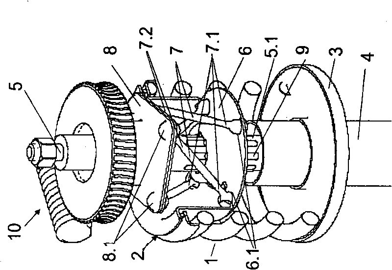
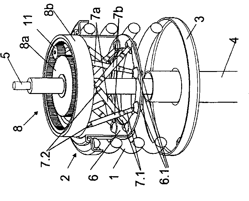
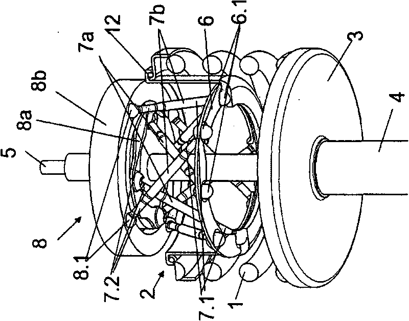
[0028] figure 1 The foot point adjustment mechanism of the spring 1 of the vehicle chassis is briefly shown. Here, a spring 1 in the form of a helical spring is provided. The helical spring is supported by each end on a spring retainer 2 , 3 . A shock absorber 4 is arranged centrally inside the spring 1 (coil spring), which shock absorber includes a piston rod 5 . At its other end, which is not shown, the shock absorber 4 is fastened to the wheel suspension. The first fastening element 6 is axially displaceable and mounted in a rotationally fixed manner and is coupled to the cup-shaped spring washer 2 of the spring 1 (helical spring), and the second fastening element 8 is drivable via a worm gear 10, wherein The coupling element 7 is arranged between the first and the second fixing element 6 , 8 . The spring retainer 2 placed above is pot-shaped. The first fixing element 6 forms the bottom of the basin. A seat 6 . 1 is provided in the first fastening element 6 for the fi...


PUM


Abstract

The invention relates to a low-end adjusting mechanism for vehicle suspensions and is used especially for compensating rolling and pitching motions and for leveling purposes. In said low-end adjusting mechanism for vehicle suspensions, a vehicle spring (1) that has a longitudinal axis is mounted between two spring seats (2, 3), and at least one spring seat can be adjusted in the direction of the longitudinal axis of the spring by means of rod-shaped coupling elements (7) which are hingedly mounted at both ends.

Description

technical field [0001] The invention relates to a foot point adjustment mechanism of a vehicle suspension and is used in particular for roll compensation and pitch compensation as well as level compensation. Background technique [0002] A vehicle spring known from DE 101 01 694 C5 has a spring support for supporting a helical spring tensioned between two spring parts; and an oscillation damper, The oscillation damper includes a damper tube and a piston rod attached to the vehicle. Here, a part of the piston rod and / or a part of the damper tube is arranged inside the helical spring, and at least one spring retainer is axially adjustable by means of a drive assembly comprising an electric motor and a transmission. Here, the electric motor is constructed as a ring motor with an external stator and an internal rotor. On its inner side, the rotor bears a sliding nut which axially adjusts the spring retainer support on the outside as a spindle and connected to the spring retain...

Claims


Application Information

Patent Timeline
IPC IPC(8): B60G17/02
CPCB60G2500/20B60G2204/419B60G17/021B60G2202/12B60G2202/44B60G2204/4193
Inventor W·弗罗因德D·莱措克A·基斯勒J·舒尔策
Owner ASTURIA AUTOMOTIVE SYST
Why Eureka
Try Eureka