Method for designing rotary feed-in mechanism of double-roller cold pilger mill and device thereof

A technology of cold rolling mill and feeding mechanism, which is applied in the direction of metal rolling, metal rolling, metal processing equipment, etc. It can solve the problems of large impact load, high noise, and difficult processing and assembly of the transmission mechanism, so as to overcome the impact The effect of large load, convenient maintenance and compact layout

Active Publication Date: 2010-05-19
CHINA NAT HEAVY MACHINERY RES INSTCO
View PDF0 Cites 5 Cited by
  • Summary
  • Abstract
  • Description
  • Claims
  • Application Information

AI Technical Summary

Problems solved by technology

In the prior art, cold-rolled pipe mills mostly adopt mechanical rotary feeding mechanisms, such as Maltai disc type, lever type, ejector type, cam-infinitely variable worm type and gearbox type, etc. The overall transmission mechanism is complex, There are many parts, it is difficult to manufacture and maintain, it is difficult to process and assemble, the impact load of the transmission mechanism is large during the rotary feeding process, the noise is large, the maintenance cost of the equipment is high, and some have the problem of inaccurate feeding.
In addition, the rotary feeding mechanism needs to rely on a long transmission shaft to transmit the power from the main drive, and the long transmission distance affects the accuracy of rotary feeding

Method used


Image

  • Method for designing rotary feed-in mechanism of double-roller cold pilger mill and device thereof
  • Method for designing rotary feed-in mechanism of double-roller cold pilger mill and device thereof
  • Method for designing rotary feed-in mechanism of double-roller cold pilger mill and device thereof

Examples


Embodiment 1

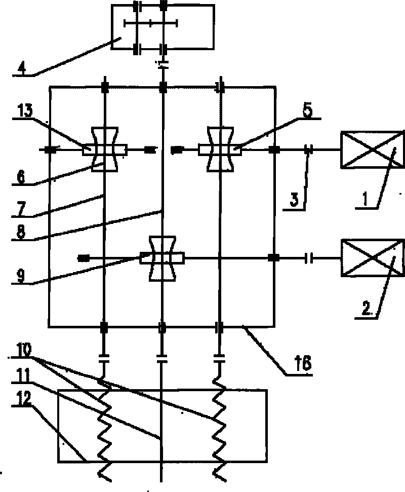
[0016] Such as figure 1 As shown, three worm gear-worm transmissions, a first worm shaft 5, a second worm shaft 9 and a third worm shaft 13 are provided on the revolving feed box 16. The first servo motor 1 communicates with the first worm shaft through the coupling 3 The shaft 5 is connected, the worm wheel 6 meshes with the first worm shaft 5, the worm wheel 6 is installed on the left and right first shafts 7 through a key connection, and the left and right first shafts 7 are connected with the left and right lead screws 10 through a coupling to realize the first servo motor 1 The left and right lead screws 10 are driven to move forward. The second servo motor 2 is connected to the second worm shaft 9 through a coupling, the worm gear meshes with the second worm shaft 9, the worm gear is connected to the second shaft 8 through a key connection, and the second shaft 8 is connected to the optical rod 11 through the coupling It is connected with the tube blank chuck 12 to realiz...

Embodiment 2

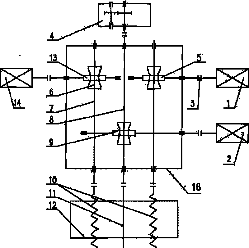
[0018] The servo motor drives the screw 10 to feed in another way, such as figure 2 Shown. Three worm gear-worm transmissions, a first worm shaft 5, a second worm shaft 9 and a third worm shaft 13 are provided on the rotary feed box 16, and the first servo motor 1 is connected to the first worm shaft 5 through a coupling 3 , The worm wheel 6 meshes with the first worm shaft 5, the worm wheel 6 is installed on the right first shaft 7 through a key connection, and the right first shaft 7 is connected with the right screw 10 through a coupling, so that the first servo motor 1 drives the right screw The bar 10 is sent into motion. The third servo motor 14 is simultaneously connected to the third worm shaft 13 through the coupling 3, the worm wheel 6 meshes with the third worm shaft 13, the worm wheel 6 is mounted on the first shaft 7 on the left by a key connection, and the first shaft 7 on the left is connected by the coupling The shaft device is connected with the right screw 1...

Embodiment 3

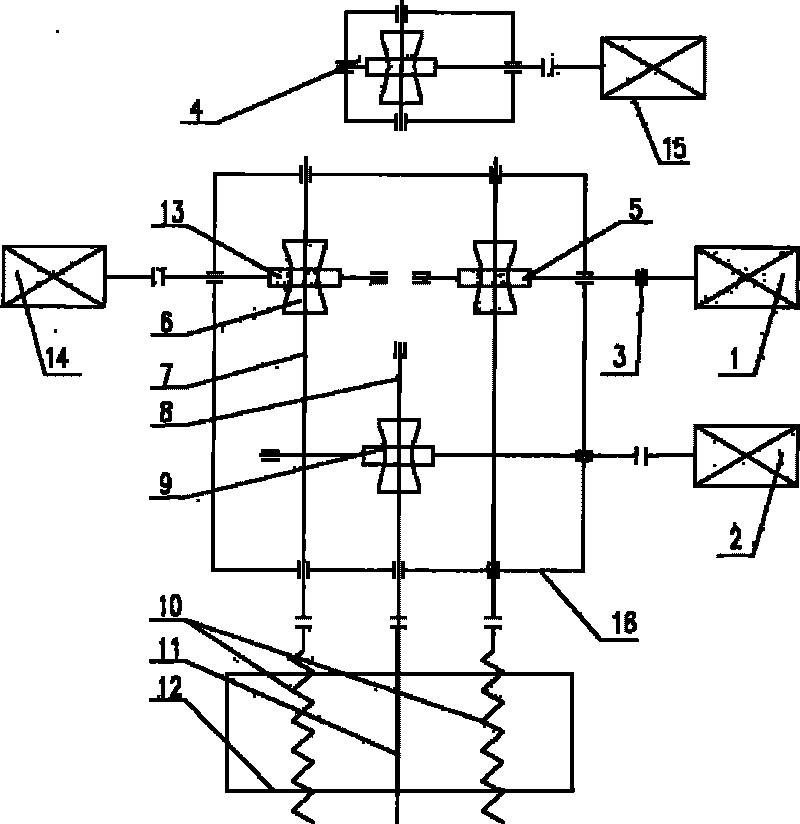
[0021] The third method used by the servo motor to drive the lead screw 10 to feed movement, such as image 3 Shown, with figure 2 The difference is that the rotary feeding box 16 is driven by four servo motors, the first servo motor 1, the second servo motor 2 and the third servo motor 14 are driven by three servo motors to drive the lead screw 10 to feed and the light rod 11 to rotate. The fourth servo motor 15 directly drives the gear transmission connected to the mandrel clamping mechanism 4, instead of being powered by the rotary feeding mechanism.


PUM


Abstract

The invention belongs to the field of metallurgical equipment, and in particular relates to a method for designing the rotary feed-in mechanism of a double-roller cold pilger mill and a device thereof. The method and the device are characterized in that: the rotary feed-in box of the rotary feed-in mechanism of the double-roller cold pilger mill is provided with three worm gearings, wherein two worm gearings are used for connecting a screw rod so as to realize feed-in motion of the screw rod; another worm gearing is used for connecting a light bar so as to realize rotary motion of the light bar and a tube blank chuck; the screw rod and the light bar are arranged on the lathe bed of the cold pilger mill; the lathe bed is arranged at one end of the rotary feed-in box; a mandril clamping mechanism is arranged at the other end of the rotary feed-in box; and the three worm gearings are driven by a servo motor. The invention provides the method for designing the rotary feed-in mechanism of the double-roller cold pilger mill and the device thereof, which have the advantages of simple structure, stable and accurate rotary feed-in and little impact load.

Description

Technical field [0001] The invention belongs to metallurgical equipment, in particular to a method and device for designing a rotary feeding mechanism of a two-roll cold rolling pipe mill. Background technique [0002] With the development of my country’s economy, in recent years there has been a large demand for large-diameter cold-rolled products in fields such as nuclear power, thermal power, fertilizer, chemical industry, chemical fiber, medicine and health, food, oil drilling, bearing manufacturing, coal mining, aerospace and military industry. At the same time, my country also exports a large number of steel pipes to foreign countries every year. Therefore, the market demand for large two-roll cold-rolling pipe mills is increasing year by year. According to relevant statistics, my country’s annual demand for cold-rolling pipe mills is about 600. Most of these rolling mills have low technical level and low production efficiency, which cannot meet the requirements of my countr...

Claims


Application Information

Patent Timeline
Patent Type & Authority Applications(China)
IPC IPC(8): B21B39/02
Inventor 阎雪峰成海宝李为纪松山展京乐郭琳李小荣曹世奇凡明
Owner CHINA NAT HEAVY MACHINERY RES INSTCO
Why Eureka
Try Eureka