

Novel optical fiber temperature and pressure sensor
A pressure sensor, optical fiber temperature technology, used in thermometers, fluid pressure measurement using optical methods, thermometers with physical/chemical changes, etc. Problems such as processing leveling and polishing
- Summary
- Abstract
- Description
- Claims
- Application Information
AI Technical Summary
Problems solved by technology
Method used
Image

Examples
Embodiment Construction
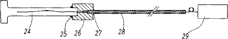
[0019] image 3 It is a typical connection mode when the present invention actually measures oil well pressure and temperature; the optical fiber temperature and pressure sensor 24 is fixedly welded on the left side of the connection seat 26 and placed downhole, the right side of the connection seat 26 is connected to the optical cable 28, and the optical cable 28 is connected to the demodulator 29.
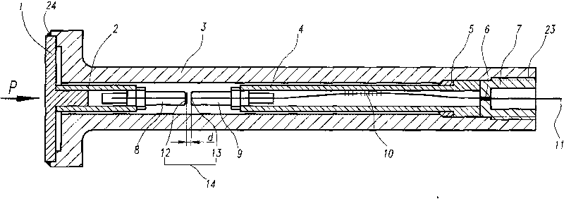
[0020] figure 1 It is a schematic diagram of the overall structure of an optical fiber temperature and pressure sensor, which includes an elastic diaphragm 1, a fiber Bragg grating 10 and a demodulator 29 connected thereto. The center of the elastic diaphragm 1 is provided with a raised column, and the elastic diaphragm 1 The edge is sealingly joined to the bell mouth of the front end of the outer protection cylinder 3, and the short connecting pipe 2 is fixedly fitted on the protruding column, and a hollow rod is fixedly arranged at the other end of the short connecting pipe 2, ...
PUM
 Abstract
Description
Claims
Application Information