Novel optical fiber temperature and pressure sensor

A pressure sensor, optical fiber temperature technology, applied in thermometers, fluid pressure measurement using optical methods, thermometers with physical/chemical changes, etc.

Active Publication Date: 2012-09-26
LASER RES INST OF SHANDONG ACAD OF SCI
View PDF6 Cites 1 Cited by
  • Summary
  • Abstract
  • Description
  • Claims
  • Application Information

AI Technical Summary

Problems solved by technology

At high temperature, the diaphragm is easy to oxidize, which reduces the reflectivity, and the deformation of the diaphragm under high pressure will make the reflective end face deformed and uneven, so that the signal of the FA-P cavity becomes weak or disappears.
However, the end face of the bare optical fiber is difficult to process and polish, and the sensor is difficult to manufacture.

Method used


Image

  • Novel optical fiber temperature and pressure sensor
  • Novel optical fiber temperature and pressure sensor
  • Novel optical fiber temperature and pressure sensor

Examples


Embodiment Construction

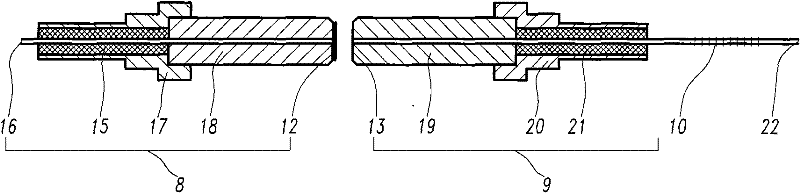
[0023] The second ceramic ferrule assembly 9 includes a cylindrical second metal connector 20 and a second ceramic rod 19 with a central hole, one end of the second metal connector 20 is inserted into the long connecting pipe 4 and fixedly connected thereto, The other end of the second metal connector 20 is fixed with a second ceramic rod 19 , and a second optical fiber 22 is fixed between the second metal connector 20 and the second ceramic rod 19 by high temperature resistant glue.

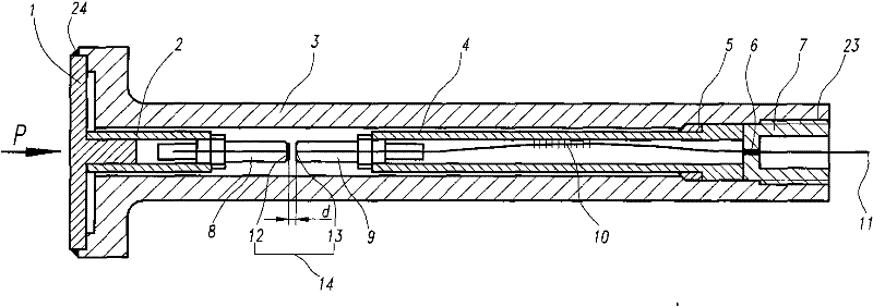
[0024] A regulating pipe 5 is sleeved on the outside of the long connecting pipe 4 . The FAP cavity 14 is used to detect pressure, and the fiber Bragg grating 10 is used to detect temperature and perform temperature compensation on the FAP cavity 14 . The FA-P cavity 14 is composed of a first ceramic ferrule assembly 8 and a second ceramic ferrule assembly 9 .

[0025] like figure 2 As shown, the first optical fiber 16 is bonded to the first ceramic rod 18 and the first metal connector 17 wit...


PUM

PropertyMeasurementUnit
thicknessaaaaaaaaaa
diameteraaaaaaaaaa
wavelengthaaaaaaaaaa

Abstract

The invention relates to a novel optical fiber temperature and pressure sensor, which comprises an elastic diaphragm, an optical fiber Bragg grating and a demodulator connected with the optical fiber Bragg grating, wherein a short connecting pipe is sleeved on a raised column of the elastic diaphragm; the other end of the short connecting pipe is fixedly provided with a hollow rod; the hollow rodand the end face of a first optical fiber in the center thereof form a first reflecting surface through polishing; a reflecting film is plated on the first reflecting surface; the other end of an outer protection tube is inserted into a long connecting pipe with a second ceramic ferrule component; the bending part of a second optical fiber is provided with the optical fiber Bragg grating; a second ceramic rod and the end face of the second optical fiber in the center thereof form a second reflecting surface through polishing; and the first reflecting surface of the hollow rod and the second reflecting surface of the second ceramic ferrule component are centered and are provided with a space therebetween to form a Fabry-Perot cavity. The optical fiber temperature and pressure sensor is used for manufacturing optical fiber sensors.

Description

technical field [0001] The invention relates to a novel sensor for simultaneously measuring temperature and pressure, especially a sensor suitable for temperature and pressure monitoring under high-temperature and high-pressure oil wells, which has very important significance for oil field exploitation. Background technique [0002] Real-time monitoring of downhole pressure, temperature and other parameters to understand the physical state of downhole oil layers is one of the important measures to optimize oil recovery technology solutions and improve oil and gas recovery and production. In the production process of heavy oil fields, in order to increase oil production, high-temperature steam needs to be injected into oil wells. The downhole temperature is as high as 350°C and the pressure reaches 30MPa. Traditional electronic pressure sensors cannot work normally in such a high temperature and high pressure environment. In the early 1980s, Pruett introduced the capillary p...

Claims


Application Information

Patent Timeline
Patent Type & Authority Patents(China)
IPC IPC(8): E21B47/06E21B47/07G01K11/32G01L11/02G01K11/3206
Inventor 刘小会王昌刘统玉吕京生田民政
Owner LASER RES INST OF SHANDONG ACAD OF SCI
Why Eureka
Try Eureka