
Method and circuit for realizing isolation of alternating current and direct current of double inverse uninterruptable power supply

A dual-inverter, AC-DC technology, applied in the conversion of AC power input to AC power output, AC power input conversion to DC power output, electrical components, etc., can solve the problem of UPS overall efficiency decline, large transformer volume, and high cost Advanced problems, to achieve the effect of reducing manufacturing costs, saving hardware resources, and reducing losses

Active Publication Date: 2010-05-19
AVIC TECH XIAMEN ELECTRIC POWER TECH CO LTD
View PDF5 Cites 3 Cited by
  • Summary
  • Abstract
  • Description
  • Claims
  • Application Information

AI Technical Summary

Problems solved by technology

At present, the solution commonly used in the industry is to add an input isolation transformer to the AC input end of the UPS; although this solution is simple to implement and requires little modification to the UPS, it also has several disadvantages: 1. The transformer is large in size and heavy. Heavy
2. There is a problem of conversion efficiency; since the efficiency of the isolation transformer is generally between 92% and 95%, the efficiency of the UPS will decrease; at the same time, the lost energy will be dissipated in the form of heat, giving The heat dissipation system of the whole machine brings a certain pressure
3. Higher cost

Method used


Image

  • Method and circuit for realizing isolation of alternating current and direct current of double inverse uninterruptable power supply
  • Method and circuit for realizing isolation of alternating current and direct current of double inverse uninterruptable power supply
  • Method and circuit for realizing isolation of alternating current and direct current of double inverse uninterruptable power supply

Examples


Embodiment Construction

[0037] The present invention will be further described in conjunction with the accompanying drawings and specific embodiments.

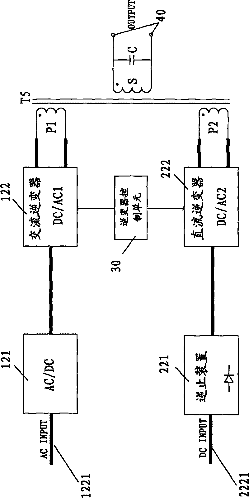
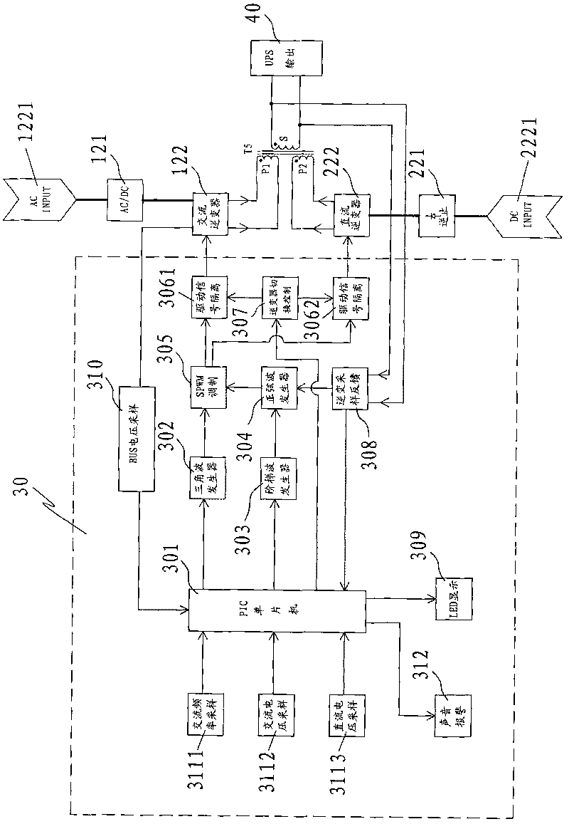
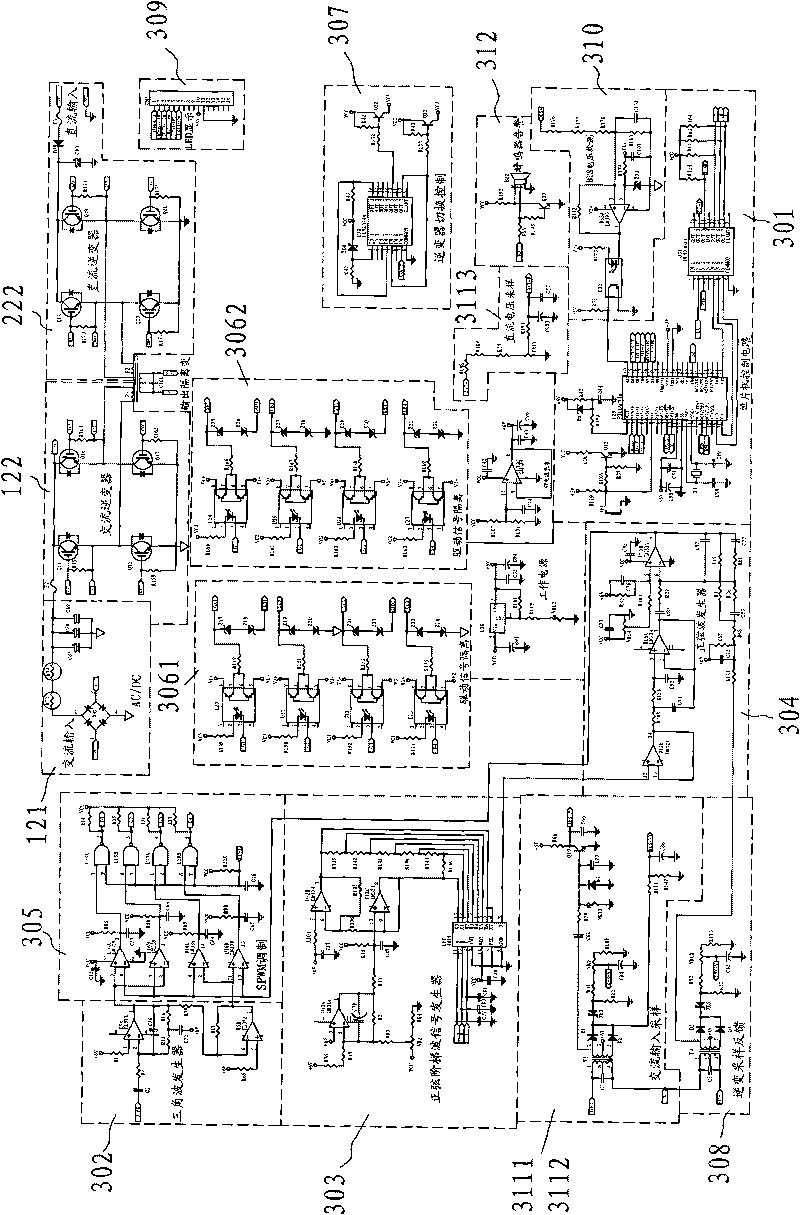
[0038] refer to figure 1 Shown is the principle main block diagram of a best implementation circuit of the present invention. Among them, after the AC input power supply 1221 is connected to the rectifier circuit 121 and the AC inverter 122, it is connected to the first primary winding P1 of the isolation transformer T5, and then coupled and output by the secondary winding S of the output isolation transformer T5, forming an AC inverter channel After the DC input power supply 2221 is connected to the backstop device 221 and the DC inverter 222, it is connected to the second primary winding P2 of the output isolation transformer T5, and then coupled and output by the secondary winding S of the output isolation transformer T5 to form a DC inverter aisle. The non-return device 221 is a diode (Diode) or a thyristor (SCR). The inverter control unit 30 ...


PUM


Abstract

The invention relates to the field of an inverse uninterruptable power supply (UPS), in particular to the realization of the isolation technology of alternating current and direct current of the double inverse uninterruptable power supply. The method and circuit for realizing isolation of alternating current and direct current of the double inverse uninterruptable power supply is used for carrying out electrical isolation on the alternating inverse circuit with alternating current input and the direct inverse circuit with current circuit input, wherein the alternating input power supply (1221) passes through the rectifying circuit (121) and an alternating current inverter (122), is sent to the first primary winding (P1) of an output isolation transformer (T5) and is output via the secondary winding (S) of the output isolation transformer (T5) in a coupled manner to constitute an alternating inverse channel; the direct current input power supply (2221) passes through an inverted device (221) and a direct current inverter (222), is sent to the second winding (P2) of the output isolation transformer (T5) and is output via the secondary winding (S) of the output isolation transformer (T5) to constitute the direct current inverse channel.

Description

technical field [0001] The invention relates to the field of inverter uninterruptible power supplies (UPS), in particular to a technology for realizing AC-DC isolation of double inverter uninterruptible power supplies. Background technique [0002] Uninterruptible power supply (UPS) is a stable, pure, uninterrupted high-quality power supply. With the rapid development of information technology and the wide application of computers, it has become an indispensable power supply device in power control systems. In the entire power control system, the backup DC power of the UPS is taken from the DC bus in the DC system; at the same time, in order not to increase the working pressure of the high-frequency rectifier module on the DC bus, the UPS uses the power of the AC grid when it works normally. The power grid is switched to the DC bus for power supply (that is, the UPS is not working in a pure inverter state). The DC system is responsible for providing reliable working power f...

Claims


Application Information

Patent Timeline
IPC IPC(8): H02M5/443H02M7/537
Inventor 巫良生陈文全林火土林东权
Owner AVIC TECH XIAMEN ELECTRIC POWER TECH CO LTD
Learn More