Electroplating clamp for printed circuit board (PCB)

A technology for printed circuit boards and electroplating fixtures, applied in the electrolytic process, electrolytic components, etc., can solve the problems of affecting efficiency, affecting the uniformity of electroplating, damage to the plated parts, etc., to improve production efficiency, avoid fixing methods, and improve good quality. rate effect

Active Publication Date: 2010-05-26
SHENZHEN WUZHU TECH
View PDF0 Cites 23 Cited by
  • Summary
  • Abstract
  • Description
  • Claims
  • Application Information

AI Technical Summary

Problems solved by technology

[0009] Aiming at the problems existing in the prior art printed circuit board electroplating jigs that easily cause damage to the plated parts, affect the uniformity of electroplating, and affect the efficiency, the present invention provides a method that can avoid damage to the plated parts, improve the uniformity of electroplating and improve Printed Circuit Board Plating Fixtures for Productivity

Method used


Image

  • Electroplating clamp for printed circuit board (PCB)
  • Electroplating clamp for printed circuit board (PCB)
  • Electroplating clamp for printed circuit board (PCB)

Examples


Embodiment Construction

[0024] The structure of the printed circuit board electroplating jig of the present invention will be described below with reference to the accompanying drawings.

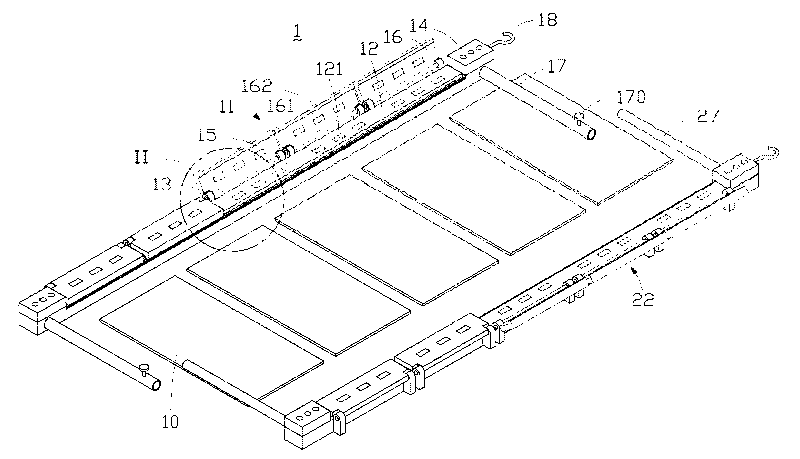
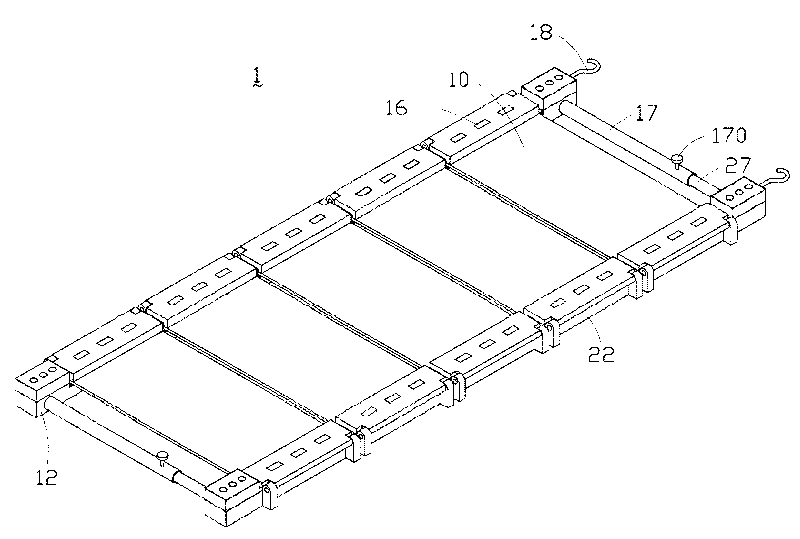
[0025] see figure 1 , is an exploded schematic diagram of a three-dimensional structure of a preferred embodiment of the printed circuit board electroplating jig of the present invention. The printed circuit board electroplating jig 1 is mainly used to clamp components to be electroplated, such as the printed circuit board 10 , and can also be used to clamp other suitable components to be electroplated. The printed circuit board electroplating jig 1 includes a first clamping part 11 and a second clamping part 22 .

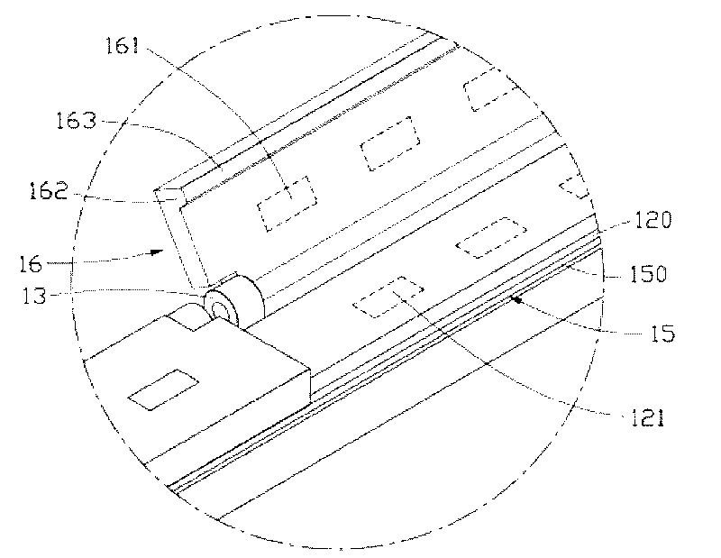
[0026] The first clamping part 11 includes a main body 12 , a pivot 13 , a fixed end 14 , an electrode 15 , a clamping cover 16 , a sleeve 17 and a hook 18 . The main body 12 , the pivot 13 , the fixed end 14 and the clamping cover 16 are made of rigid insulating material, such as polycarbonate (Polyc...


PUM


Abstract

The invention provides an ultrathin magnetic fixed type electroplating clamp for a printed circuit board (PCB), which is used for clamping the PCB. The electroplating clamp for the PCB comprises a first clamping part, wherein the first clamping part comprises a main body and a clamping cover; the main body comprises a first magnet; the clamping cover comprises a second magnet; and the first magnet and the second magnet mutually attract to enable the main body and the clamping cover to together clamp the edge of the PCB. The electroplating clamp for the PCB of the invention can prevent electroplated components from being damaged, can increase the electroplating uniformity and can improve the production efficiency.

Description

technical field [0001] The invention relates to an electroplating jig for a printed circuit board, in particular to an electroplating jig for an ultra-thin magnetic solid printed circuit board. Background technique [0002] The main purpose of electroplating is to improve the decoration, corrosion resistance, wear resistance, weldability and optical, electrical and magnetic properties of the appearance of the plated parts for the interconnection between double-sided and multi-layer. The coating generally needs to be several microns (um) to tens of microns thick. Electroplating surface treatment methods are widely used in industry because of the simple electroplating process equipment, easy control of operation, low cost and diversity of coating functions. [0003] For larger-sized pieces to be plated, when they are placed in the electroplating tank, an electroplating fixture is required to clamp the piece to be plated, and then a DC power supply is applied for electroplatin...

Claims


Application Information

Patent Timeline
Patent Type & Authority Applications(China)
IPC IPC(8): C25D17/08
Inventor 冉彦祥
Owner SHENZHEN WUZHU TECH
Why Eureka
Try Eureka